


Maintenance and Servicing
GENERAL
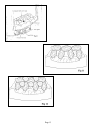
A. REMOVAL OF DEBRIS OR SOOT DEPOSITS
Allow the appliance to cool sufficiently before removing all of the coals and firebed components for cleaning
purposes. Once all the ceramics are removed from the firebed check that no debris is located in the burner
slots (both front and rear). If any debris is present it may easily be removed by using a small piece of thin
cardboard to ease out any foreign matter. Be sure to remove the cardboard after use. To ensure that the
release of fibres from these RCF articles is kept to a minimum, during installation and servicing we
recommend that you use a HEPA filtered vacuum to remove any dust and soot accumulated in and around
the fire before and after working on the fire. When replacing these articles we recommend that the replaced
items are not broken up, but are sealed within heavy duty polythene bags, clearly labelled as RCF waste.
This is not classified as "hazardous waste" and may be disposed of at a tipping site licensed for the disposal
of industrial waste. Protective clothing is not required when handling these articles, but we recommend you
follow the normal hygiene rules of not smoking, eating or drinking in the work area and always wash your
hands before eating or drinking. Any sooty deposit on the thermocouple probe can be cleaned off using a
non-fluffy cloth.
DO NOT USE ABRASIVE MATERIALS
B. SERVICING COMPONENTS BELOW THE BURNER ASSEMBLY
(Turn OFF the gas supply to the appliance.)
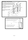
Remove coals, coal supports, burner inserts and front simulated coal. To gain access to components below the
burner assembly it has to be removed from the vent box case by disconnecting the gas supply at the inlet
elbow and unscrewing the two screws on the sides of the facia panel. Where the supply is fed from the right
hand side across the front of the fire it will be necessary to disconnect the supply from the isolation tap/elbow.
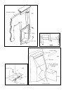
i) TO CLEAN OR REPLACE THE INJECTOR: Remove the aeration sleeve retaining screw unscrew
the compression nut connecting the gas supply to the elbow injector while supporting the injector to prevent
distortion of the framework. Unscrew and remove the gas supply tube from the gas control valve, hold the
injector lock nut with a spanner and rotate the injector. Replace in reverse order - ensure the aeration sleeve
retaining screw is replaced.
ii) TO REPLACE THE GAS CONTROL (Tap/FSD): Disconnect the three gas pipes and the
thermocouple from the control. Pull off the knob and lay to one side. Undo the retaining nut at the front of
the tap niting assembly to withdraw control from the mounting bracket. Replace in reverse order.
iii) TO REPLACE THE PIEZO IGNITER: Pull off the HT lead from the rear of the igniter. Retain the
metal fixing nut with one finger and rotate the body of the igniter to unscrew. Withdraw the igniter from the
front. Replace in reverse order and reconnect the HT lead.
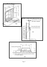
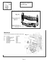
iv) TO REPLACE THE OXY-PILOT ASSEMBLY: The assembly is not an item that can be serviced as
part of its calibration depends on the proximity of the spark electrode and thermocouple tip. The assembly can
be replaced by removing the tube nut and tube from the base of the pilot and the thermocouple from the FSD
also the igniter lead and the two screws securing the bracket to the framework. Replace in reverse order, the
spark gap is shown in fig 14.
Page 8