


TF-SERIES INSTALLATION, OPERATION AND SERVICE MANUAL
14
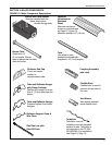
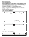
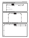
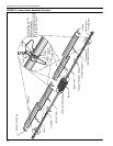
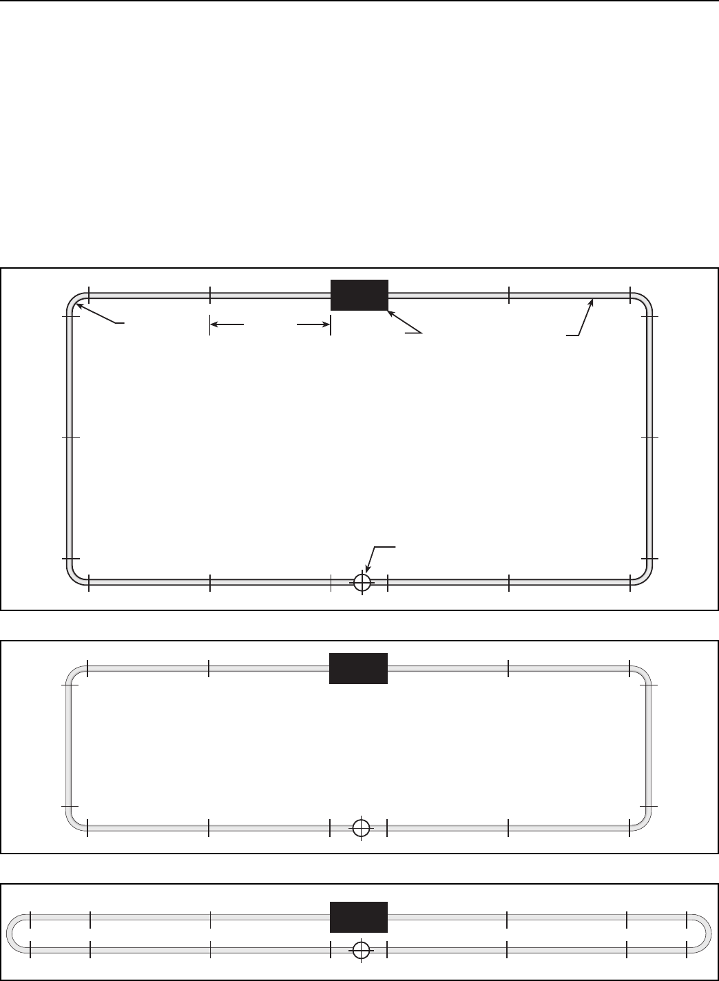
SECTION 6: SUGGESTED LAYOUTS
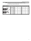
The following are suggested layouts for the heater. These layouts are effective in maximizing the heat pattern
and overall performance of the heater. All heaters can be common vented or individually vented (See Page
37, Section 9) depending on the building requirements. These are only suggested layouts. The heater can be
designed in various configurations provided they are in the guidelines of this manual. When designing a U-
Tube or Elbow configuration, the following rules must be adhered to:
• A minimum of 10' (3 m) of tubing on TF-120/160 and/or a minimum of 15' (4.5 m) of
tubing on the TF-200/250/300/350/380 is required between the burner and the Elbow or U Tube.
• The design and installation must adhere to the rules and guidelines located in this manual (See Page 16,
Section 7 and Page 37, Section 9).
• Review
venting options before selecting a layout.
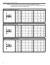
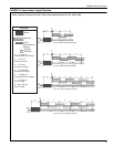
6.1 TF-380 - 4 Elbow Design (Common Vent)
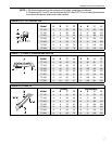
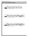
6.2 TF-350 - 4 Elbow Design (Common Vent)
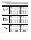
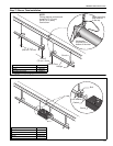
6.3 TF-300 - Double "U" Design (Common Vent)
10' Typ.
(3 m)
Burner
Tube
Common Vent
90° Elbow