


TF-SERIES INSTALLATION, OPERATION AND SERVICE MANUAL
8
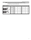
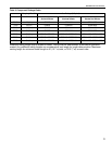
NOTE: 1. All dimensions are from the surfaces of all tubes, couplings and elbows.
2. Clearances B, C and D can be reduced by 50% after 25' (7.5 m) of tubing downstream
from where the burner and burner tube connect.
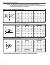
*When installed in the first 10’ (3 m) on each side of the burner.
**Roberts-Gordon prohibits the installation of this heater for all unapproved applications.
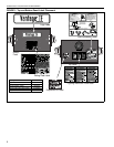
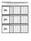
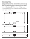
FIGURE 9: U-TUBE, OPPOSITE 45
° REFLECTOR
(inches) (centimeters)
Model ABCDABCD
TF-120 8 54 60 22 21 138 153 56
TF-160 8 6066222115316856
TF-200 10 64 74 22 26 163 188 56
TF-250 10 70 78 22 26 178 199 56
TF-300 12 74 84 22 31 188 214 56
TF-350 12 76 85 22 31 194 216 56
TF-380 12 76 85 22 31 194 216 56
A
C
D
B
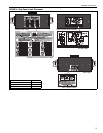
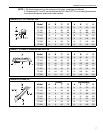
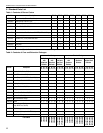
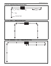
FIGURE 10: 2-FOOT DECO GRILLE AND PROTECTIVE GRILLE
(inches) (centimeters)
Model ABCDABCD
TF-120 6 35 63 35 16 89 161 89
TF-160 6 38 66 38 16 97 168 97
TF-200 6 40 71 40 16 102 181 102
TF-250 6 46 77 46 16 117 196 117
TF-300 6 50 80 50 16 127 204 127
TF-350 8 52825221133209133
TF-380 8 52 82 52 21 133 209 133
A
C
D
B
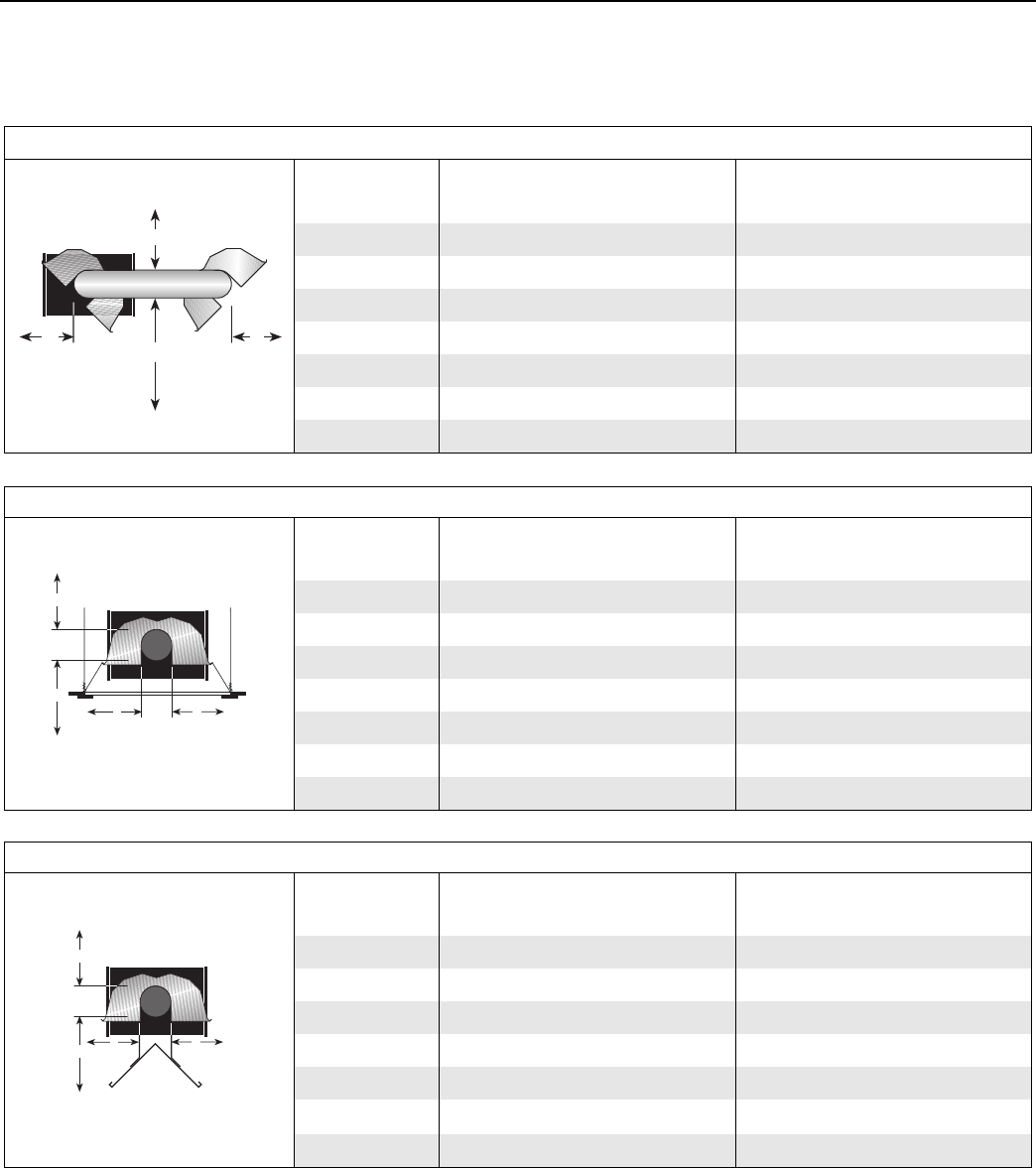
FIGURE 11: LOWER CLEARANCE SHIELD*
(inches) (centimeters)
Model ABCDABCD
TF-120 6 39 33 39 16 100 84 100
TF-160 6 40 38 40 16 102 97 102
TF-200 6 50 44 50 16 127 112 127
TF-250 6 54485416138122138
TF-300 6 55 50 55 16 140 127 140
TF-350**
Unapproved Unapproved
TF-380**
Unapproved Unapproved
A
C
D
B