


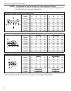
SECTION 3: CLEARANCES TO COMBUSTIBLES
7
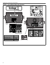
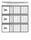
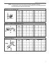
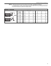
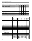
NOTE: 1. All dimensions are from the surfaces of all tubes, couplings and elbows.
2. Clearances B, C and D can be reduced by 50% after 25' (7.5 m) of tubing downstream
from where the burner and burner tube connect.
FIGURE 6: 45
° TILT REFLECTOR
(inches) (centimeters)
Model ABCDABCD
TF-120 8 8 60 54 21 21 153 138
TF-160 8 8 66 60 21 21 168 153
TF-200 10 8 74 64 26 21 188 163
TF-250 10 8 78692621199176
TF-300 12 8 84 74 31 21 214 188
TF-350 12 8 85793121216201
TF-380 12 8 85 79 31 21 216 201
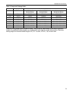
FIGURE 7: U-TUBE, STANDARD REFLECTOR
(inches) (centimeters)
Model ABCDABCD
TF-120 6 35 63 30 16 89 161 77
TF-160 6 386937169717694
TF-200 6 40 76 39 16 102 194 100
TF-250 6 46794316117201110
TF-300 6 50 84 47 16 127 214 120
TF-350 8 54875121138221130
TF-380 8 54 87 51 21 138 221 130
A
C
D
B
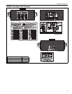
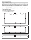
FIGURE 8: U-TUBE, 45°
(inches) (centimeters)
Model ABCDABCD
TF-120 8 8 60 42 21 21 153 107
TF-160 8 8 66 46 21 21 168 117
TF-200 8 8 74 52 21 21 188 133
TF-250 8 8 78 61 21 21 199 155
TF-300 8 8 84 66 21 21 214 168
TF-350 8 8 85 70 21 21 216 178
TF-380 8 8 85 70 21 21 216 178
B
C
D
A