


– 19 –
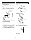
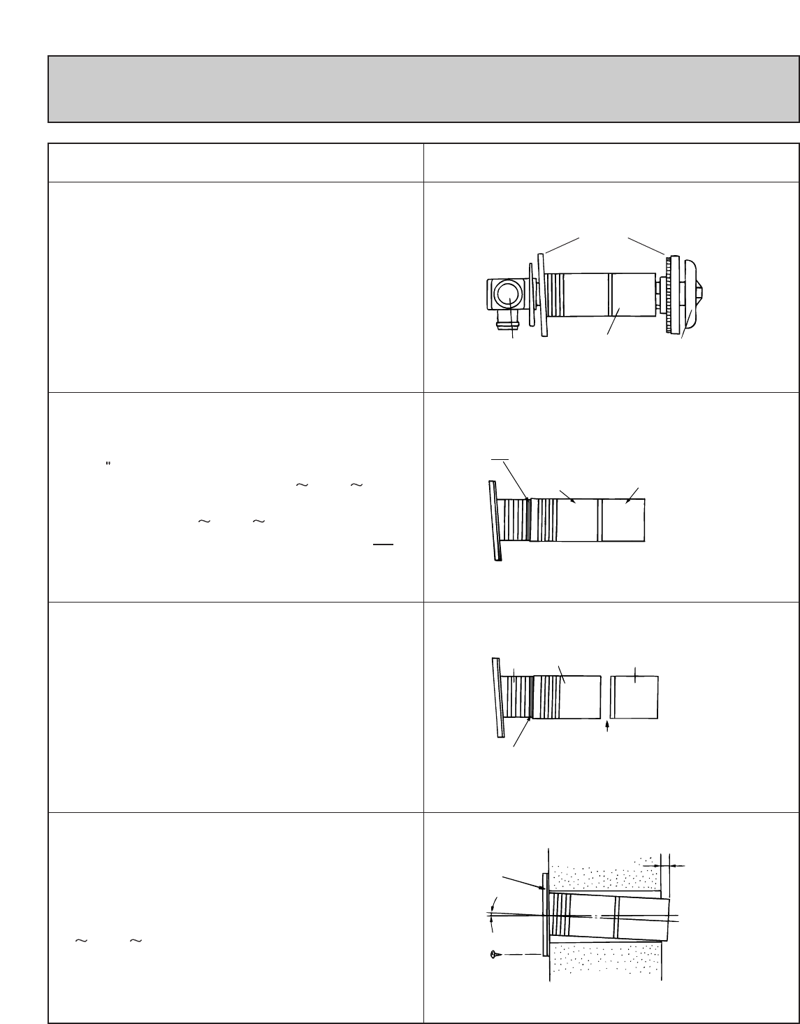
SLEEVE AND MANIFOLD INSTALLATION
METHOD FOR STANDARD WALLS
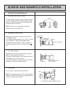
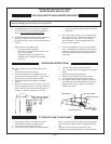
1. Disassemble Manifold from Sleeve.
The flue consists of 3 parts, sleeve, inside connectors
and tube, outside terminal; (dis-assembly by pulling
hard on outside terminal and inner connections, then
pull sleeve off outer terminal.)
NOTE: Clearance to combustibles for terminal
assembly sleeve and flanges is 0".
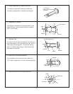
2. Adjustment of Sleeve Length.
Measure wall thickness through previously drilled
3 1/8
(80mm) hole.
End of sleeve should protrude 3/16" 3/8" (5 10mm)
from outside wall. Adjust sleeve length to wall
thickness plus 3/16" 3/8" (5 10mm). (Sleeve is
threaded for adjustment.) Do not extend beyond red
line.
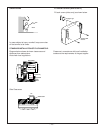
3. For S and A flue only.
Depending on flue set and wall thickness extension
piece “C” may need to be removed.
Cut plastic, remove extension, then follow instruction 2.
This applies to “S” and “A” flues only.
There is no extension on other flues, they can be fully
adjusted by turning the threaded section.
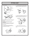
4. Fixing Sleeve.
Fix to the wall, using the 3 screws provided.
NOTE: The flange is marked “TOP”, sleeve must be
fitted with this mark
Up. Check sleeve protrudes 3/16"
3/8" (5 10mm) on the outside.
Connection
Sleeve
Flanges
Terminal
Extension joint
under plastic
Extension
("S" and "A" flues only)
Adjust length by turning sleeve.
Do not extend
beyond red line
A
B
C
Remove extension at this
point it necessary.
"A" Flue only
Fixing Screw
2°
"TOP"
5-10mm
Don't remove green plastic covering from sleeve.