


25
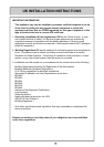
Appliance Location.
The wall or structure on which it is mounted must be capable of supporting the weight of
the appliance (15 kg) and associated pipework. Ensure that suitable screws or bolts are
used to secure the water heater to the wall. Bracket and fixing hole locations are shown
on the template included. The top bracket has a keyhole slot so that the appliance can
be hung on one screw, and then the other fixings can be added to secure the unit.
The heater must be installed in the vertical position with the gas and water connections
on the underside pointing vertically downward. The heater must be installed internally.
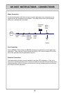
The appliance should be placed as close as practical to the most frequently used hot
water outlet point or points to minimise the delay time for hot water delivery. For
installations where the distance between the unit and hot water outlet points is
considerable, the appliance can also be fitted in a 'flow and return system' which
minimises the waiting time for hot water delivery. Alternatively, multiple appliances can
be strategically placed to service outlet points with minimal delay time. Contact Rinnai or
your supplier for further information.
When positioning appliance the flue terminal clearances must be in accordance with lo-
cal requirements. Consideration should be given to other appliances, openings, and
boundaries. Multiple heater installations can be installed with the heaters manifolded
together. The minimum distance required between the heaters may then be based on
the necessary clearances between flue terminals.
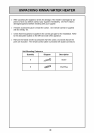
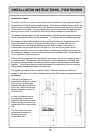
The appliance must be in an accessible location. Sufficient clearances shall allow
access to, and removal of, all serviceable components. The following clearances should
be followed.
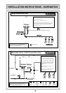
If the unit is installed on a
combustible wall such as wood
there must be a 45mm gap
between the wall and the back
of the unit. Brackets are avail-
able to space the unit this far
off of the wall.
In case the side wall next to
the appliance is flammable
material there must be at least
50mm between the side of the
appliance and the combustible
wall.
The illustration shows the
clearances necessary for
servicing, on a non-
combustible wall.
INSTALLATION INSTRUCTIONS - POSITIONING