Model RCE-229Awww.rinnaina.com 1 0
4. Any compound used on the threaded joint of gas piping shall be a type which resists the action of
liquefied petroleum gas.
5. Supplied gas pressure must be within the limits shown in the specifications.
6. After completion of gas pipe connections, all joints including the heater must be checked for
gas-tightness by means of leak detector solution, soap and water, or an equivalent nonflammable
solution, as applicable.
CAUTION: Since some leak test solutions, including soap and water, may cause corrosion
or stress cracking, the piping shall be rinsed with water after testing, unless it has been
determined that the leak test solution is noncorrosive.
7 The appliance and its appliance main gas valve must be disconnected from the gas supply piping system
during any pressure testing of that system at test pressures in excess of 1/2 psi (3.5kPa).
The appliance must be isolated from the gas supply piping system by closing its equipment shut-off valve
during any pressure testing of the gas supply piping system at test pressures equal to or less than 1/2 psi
(3.5kPa).
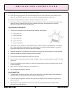
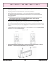
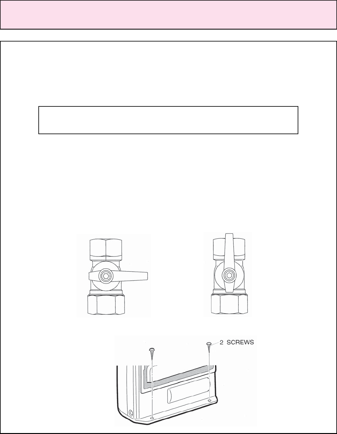
8. A valve supplied must be installed on back of unit at time of installation. This is for compliance to ANSI
standard Z21.11.2. Valve is packaged with unit.
MANUAL VALVE
CLOSED OPEN
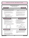
9. After completing pipework, secure the heater to the floor. Use the two screws provided, as shown in
the drawing. To prevent deforming base plate, do not over torque screws.
INSTALLATION INSTRUCTIONS


