


18
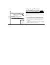
Installing the water heater:
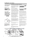
Relief Valve
A new pressure relief valve, complying
with the Standard for Relief Valves and
Automatic Gas Shut-Off Devices for Hot
Water Supply Systems, ANSI Z21.22/
CSA 4.4, must be installed at the hot
water outlet connection of the water
heater at the time of installation. Local
codes shall govern the installation of
relief valves.
For safe operation of the water heater, be
sure that:
● The pressure rating of the relief valve
must not exceed 150 psi (1034 kPa), the
maximum working pressure of the
water heater as marked on the rating
plate.
● The BTUH rating of the relief valve
must equal or exceed the BTUH input
of the water heater as marked on its
rating plate.
● No valve of any type should be
installed between the relief valve and
the water heater.
● Discharge from the relief valve should
be piped to a suitable drain to eliminate
potential water damage. Piping used
should be of a type approved for the
distribution of hot water.
● Hot and cold water lines should be
insulated up to the water heater. Refer
to page 24 for details.
● The discharge line must be NO
SMALLER than the outlet of the relief
valve and must pitch downward to
allow complete drainage (by gravity) of
the relief valve and discharge line.
● The end of the discharge line should not
be threaded or concealed and should be
protected from freezing. No valve of
any type, restriction or reducer coupling
should be installed in the discharge line.
Notice: Local codes govern the
installation of relief valves. If local codes
require that a temperature and pressure
relief valve should be installed the
manufacturer recommends a type 40XL
Watts T&P relief valve or an equivalent
model be used.
Notice: Manual operation of relief valves
should be performed at least once a year.
Turn off the electrical power and gas
shutoff valve. Lift and release lever on the
relief valve and check the manual
operation of the relief valve. You should
take precaution to avoid contact with the
hot water coming out of the relief valve
and to prevent water damage.
Notice: If the relief valve on the system
discharges periodically, a problem exists
and service to the water system is
required.
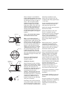
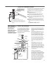
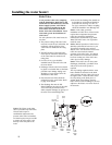
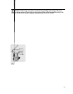
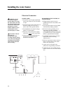
The vinyl tubing supplied with the water
heater should be connected to the drain
valve located at the hot outlet as shown in
the Figure below. Route the other end of
the vinyl tubing to the drain pan or a
suitable drain where leakage from the
heater will not result in damage to the area
adjacent to the heater or to lower floors of
the structure.
Union
Pressure
Relief Valve
Water
Shutoff
Valve
Cold
Water
Supply
Inlet
Hot Water
Supply
Outlet
Relief
Valve
Discharge
Line
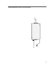
Notice: The Figure on the right
shows a pressure only relief valve.
If local codes require a
combination temperature and
pressure relief valve be installed,
an extension piece may be needed
to ensure the valve probe is not
directly in the flow path of the
water.
Drain
Tube to
suitable
drain
Drain
Valve