


17
Water Supply Connections continued.
● To supply hot water to upper floors,
additional water pressure (0.44 psi/ft)
(10 kPa/m) must be ensured. The
measurement should be calculated by
the distance between the water inlet of
the water heater (ground level) to the
hot water faucet (upper floor level).
● Well water systems should be set to
ensure a minimum system pressure of
40 psi (276 kPa).
● When the water is supplied from a
water supply tank, the height of the
tank and the diameter of the pipes and
their relation to water pressure, should
be taken into consideration. Gravity
water pressure is not recommended.
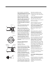
Notice: If the water flow resistance of a
shower head is too high, the burner in the
water heater will fail to ignite. Keep the
shower head clean from debris that could
cause additional pressure drop.
Notice: If using mixing valves on the
outlet, choose one which prevents cold
water pressure from overcoming hot water
line pressure.
Notice: If multiple water heaters are
installed in a manifold system, the
water piping must be in “Parallel”. A
water pressure of 40 psi (276 kPa) is
recommended for each water heater for
proper operation of the water heaters.
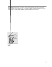
Install a shutoff valve near the inlet of the
water heater for service and draining
purposes.
It is not recommended to use pipes with
smaller diameters than the water supply
connection of the water heater.Before
connecting the water supply pipe to the
water heater, open the shutoff valve and
clean out sand, debris, air, caulking
material, etc. inside the pipe. Connect to
the water inlet, then check water flow.
Close the shutoff valve and clean the
water filter.
Be sure to connect the water inlet and the
hot water outlet as shown on the water
heater. If reversed, the water heater will
not function.
Installation of unions or flexible copper
connections are recommended on the
HOT and COLD water lines, so that the
water heater may disconnect easily for
servicing if necessary.
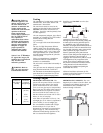
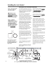
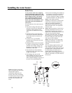
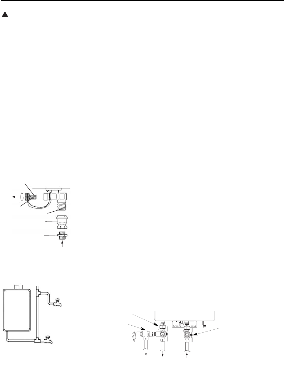
Install a Check Valve between the water
heater and the water shutoff valve. (See
Figure on the left).
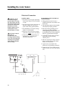
The following should be addressed in
regards to the HOT WATER OUTLET:
● Connections between the water heater
and point(s) of use should be as short
and direct as possible.
● Local codes shall govern the exact type
of pipe material that is to be used for
water connections.
● To conserve energy and minimize heat
loss, insulation of hot water piping is
recommended. (See Hot and Cold Pipe
Insulation Installation on page 24).
Notice: The flow rate of hot water may
vary when more than two faucets
(appliances, fixtures, etc.) are being used
simultaneously.
Notice: The pipes MUST be completely
drainable. If the hot water faucets are
located at a point higher than the water
CAUTION: This water
heater must only be used
with the following water
supply system conditions:
● With clean, potable water
free of corrosive
chemicals, sand, dirt, or
other contaminates.
● With inlet water
temperatures above
32°F (0°C), but not
exceeding 120°F (49°C)
for Light Duty models
and up to 140°F (60°C)
for Heavy Duty models.
● Free of lime and scale
deposits.
● DO NOT reverse the hot
and cold water
connections. The water
heater will not operate.
!
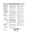
Water Filter
Check Valve
Water Inlet
Clean the
Water Filter
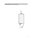
Water
Nipple
Air
Relief
Va lv e
Hot
Wate
Tap
Drain Valve
Notice: Use only teflon tape
on cold and hot water
connections and lines.
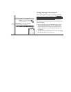
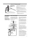
Hot Water Tap
Water Inlet
Water Outlet
Drain
Pressure Relief Valve
Hot Water Service Valve
Cold Water Service
Valve
Alternate Piping Arrangement