


15
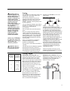
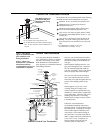
Vertical Vent Installation
A fire stop plate should be installed at
every penetration of a floor or ceiling if
the vent is not running in a fire-rated
shaft. Maintain the recommended air
space clearance to combustible materials
and building insulation.
Once the vent terminal location has been
determined, make a hole through the roof
and interior ceiling to accommodate the
vent pipe.
Install adequate flashing where the vent
pipe passes through the roof. Determine
the vent terminal height and install the
vent pipe accordingly. Refer to the Figure
above for proper vent terminal height.
The vent roof system must terminate at
least 1 foot (30 cm) above the roof line
and at least 2 feet (60 cm) higher than any
portion of the building within 10 feet
(3 m).
Install supports every 5 feet (1.5 m)
vertically along the vent pipe route.
Vertical supports are required after every
transition to vertical and are required after
every offset elbow. When the vent is free
standing and penetrates a roof/ceiling
another means of support must be used at
a second location.
Follow the vent manufacturers
recommended installation instructions
provided with the vent kit purchased from
the manufacturer. Complete the vent pipe
and air intake adapter installation to the
water heater’s vent connector fitting on
the water heater vent collar outlet and air
intake. Support vertical or horizontal runs
every 5 feet (1.5 m). If required, use
silicone sealant at the point the vent
connector joins the water heater.
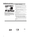
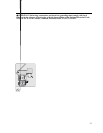
Chase Requires
6” (15 cm) Clearance
to Combustibles
Firestop
Firestop
Tall Cone
Flashing
Vent
Adapter
3” (8 cm)
Clearance
Condensate
Trap
To Drain. Dispose of
condensate in accordance
to local codes
Storm Collar
Support Clamp
1/4” per foot upward slope
3’
(91 cm)
Max
Support
Hanger
Vertical
Termination
Adapter
(Rain Cap)
Vent Outlet
Air Intake
4“/ 7” Concentric Pipe
Standard Vertical Vent Termination
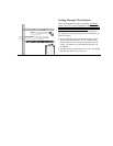
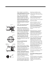
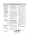
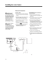
Vertical Vent Termination Location
The location of the vent terminal depends on the following
minimum clearances and considerations (see Figure):
Minimum twelve (12) inches
(30 cm)
above roof.
2
Minimum twelve (12) inches
(30 cm)
above
anticipated snow level.
Maximum twenty-four (24) inches
(60 cm)
above
roof level without additional support for vent.
Four (4) feet
(1 m)
from any gable, dormer or other
roof structure with building interior access (i.e., vent,
window, etc.).
Ten (10) feet
(3 m)
from any forced air inlet to the
building. Any fresh or make-up air inlet such as a
dryer or furnace area is considered to be a forced air
inlet.
3
Min. 12"
(30 cm)
Above Roof
1
Min. 12"
(30 cm)
Above Anticipated Snow Level.
Max. 24"
(60 cm)
Above Roof (Without Additional Support)
Vent Pipe
Through Roof
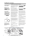
Notice: Only Rheem
approved termination and
parts should be used
during installation.
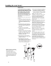
Notice: Follow vent
manufacturer’s installation
instructions and their
recommended clearances to
combustibles as required.
Only Rheem approved
termination and parts
should be used during
installation.
Air Intake Pipe
Air Intake Tee
Vent Outlet Pipe
2
For installations in Canada 18” (45.7 cm).
3
For installations in Canada 6´ (1.8 m).
1
Min. 18” (46 cm) above roof for installations. in
Canada.