


Six Months:
1. Heat Exchanger Surfaces.
a. Shut off electric and gas supply to heater.
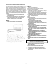
b. Examine external surfaces
2. Preliminary examination maybe done by using a
mirror and a light in the burner area.
3. Remove venting, heater jacket top, flue collector and
heat exchanger baffles. Remove inspection baffles.
c. If surfaces are sooted or foreign material is lodged
in fins, cleaning is required.
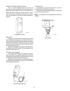
To clean:
A. Remove burner tray.
- Disconnect gas control valves and pilot valves by
breaking at unions.
- Disconnect wiring from gas valves.
- Remove burner tray retention screws.
- Slide tray from heater carefully to avoid disturbing
or damaging IID.
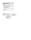
B. Remove tube bundle.
- Disconnect inlet-outlet header by removing flange
nuts and retaining bolts.
- Slide tube bundle away from inlet-outlet header,
taking care to avoid damage to refractory and
sheetmetal.
- Washdown external surfaces of tube bundle.
- Inspect interior surfaces of tubes. Clean deposits
over 1/16" thickness.
- Clean tubes using tube cleaning kit.
C. Ream tubes by using auger bit.
D. Complete cleaning by wire brushing to remove all
debris.
E. Immerse tube bundle in non-inhibited descale sol-
vent.
NOTE: DO NOT wire brush external surfaces. Steam
cleaning is a recommended procedure.
F. Replace tube bundle using the reverse of the
above procedures.
G. Before replacing burner tray clean burners.
4. Flow switch should be removed and checked.
5. Low water cutout, if provided, should be removed
and checked.
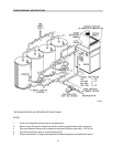
INSPECTION AND MAINTENANCE PROCEDURES
It is a good practice to make a periodic inspection of the
heater. It is recommended that the home owner or user
checks the heater after the first and third month of
operation, and then on an annual basis, or more often if
desired. It is also recommended to have a qualified
service agency check the heater before each heating
season, or at anytime there may be an indication of a
problem.
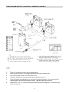
1. Keep heater area free from combustibles and
flammable liquids.
2. Be certain that
All combustion and ventilation air
openings are free and clear of all obstructions.
Screens, covering same, must be clean.
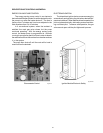
Monthly:
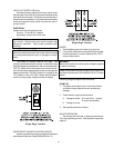
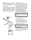
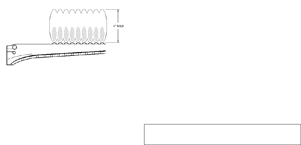
1. Make visual inspection of burner flames.
Fig. #8144
a. Flame should be blue with light yellow tips.
b. Yellow flame indicates clogged air openings.
c. Lifting of flame indicated high gas pressure.
Check using manometer at 1/8 in. NPT tapping
located between the gas valve and the burners.
Pressure should be 3.7 in. W.C.
2. Inspect and operate all controls and gas valves.
3. Visually inspect system for water leaks
33