


10 Regency
®
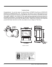
U38-1 ULTIMATE Freestanding Gas Stove
INSTALLATION
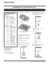
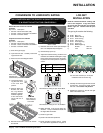
CONVERSION KIT# 731-969 FOR NG TO LP
THIS CONVERSION MUST BE DONE BY A QUALIFIED GAS FITTER IF IN DOUBT DO NOT DO THIS CONVERSION !!
1) Shut off the gas supply.
2) Open the front door and carefully
remove the logs and lava rock.
Pilot assembly is now accessible
for steps 4) to 9).
Each Kit contains one LPG
Conversion Kit and one DC
Sparker Kit.
LPG Conversion Kit Contains:
Qty. Part # Description
1 904-529 5/32" Allen Key
1 904-641 Burner Orifi ce #50
1 918-590 Label "Converted to
LPG"
1 908-528 Red "LPG" label
1 910-037 LPG Injector
(Pilot Orifi ce)
1 918-485 Instruction Sheet
DC Sparker Kit Contains:
Qty. Part # Description
1 820-475 Bracket DC Sparker
1 820-476 Bracket DC Sparker
1 904-153 Washer #8 External
Star
1 904-330 Nut 8-32 Hex
1 904-438 Plug Nylon 0.750 Hole,
Black
2 904-531 Bushing Split Plastic
0.500 in.
1 904-543 Screw 8-32 x 3/4
Pan Head
2 904-553 Screw #8 x 1/2
Type "B", Black Oxide
1 910-073 Spark Generator
Battery Holder
1 910-074 Spark Generator
Switch C/W Wire
1 910-078 Battery Size AA
Energizer En91
2 910-199 Clip Wire Holder
1 910-903 Wire Fan To Power
Cord, Ground 30 in.
904-781 Velcro Hook, Black
904-782 Velcro Hook, Black
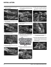
Note: Use a magnetic type screwdriver
if possible.
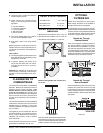
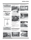
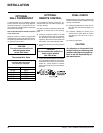
7) Turn control knob to the “OFF” position.
8) Remove the black protection cap by
hand from the high-low knob (Fig.1).
9) Insert a 5/32” or 4mm Allen wrench into
the hexagonal key-way of the screw
(Fig. 2), rotate it counter-clockwise until
it is free and extract it.
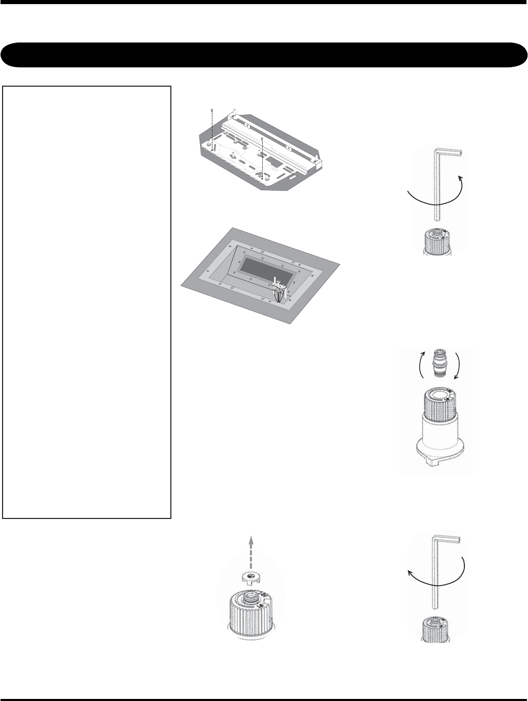
10) Check that the screw is clean and if
necessary remove dirt.
11) Flip the screw (Fig. 3).
12) Using the Allen wrench as shown in
Fig.4, rotate the screw clockwise until
snug, do not overtighten.
Fig.4
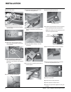
Installation of LPG
Conversion Kit:
4) Open pedestal door and remove the
gold chain from door which will allow
door to fall.
5) Remove lighting panel by removing the
6 Phillips head screws and put to the
side.
6) Remove hi-low extension knob.
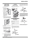
3) Remove burner. See diagram below.
Fig.1
Fig.2
Fig.3