


Regency
®
U39 ULTIMATE Direct Vent Freestanding Gas Stove
27
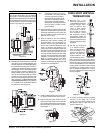
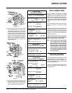
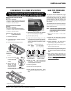
GAS PIPE PRESSURE
TESTING
The appliance must be isolated from the gas
supply piping system by closing its individual
manual shut-off valve during any pressure
testing of the gas supply piping system at test
pressures equal to or less than 1/2 psig. (3.45
kPa). Disconnect piping from valve at pressures
over 1/2 psig.
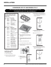
CONVERSION TO LOWER BTU RATING
THIS CONVERSION MUST BE DONE BY A QUALIFIED GAS
FITTER IF IN DOUBT DO NOT DO THIS CONVERSION !!
Natural Gas Conversion Kit 730-920
Contains:
Qty. Part # Description
1 904-240 Burner Orifi ce #37 (Natural Gas)
1 918-034 Decal "Converted to 30,000 Btu"
1 918-033 Instruction Sheet
Propane Conversion Kit 730-922
Contains:
Qty. Part # Description
1 904-390 Burner Orifi ce #52 (Propane)
1 918-034 Decal "Converted to 30,000 Btu"
1 918-033 Instruction Sheet
Additional Piece (pkg. with unit):
1 Log Bracket Restrictor
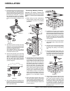
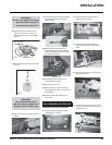
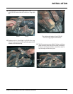
1) Shut off the gas supply.
2) Open the front door. Carefully remove the
logs and lava rock.
3) Remove burner. See diagram below.
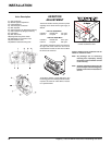
Burner Orifi ce
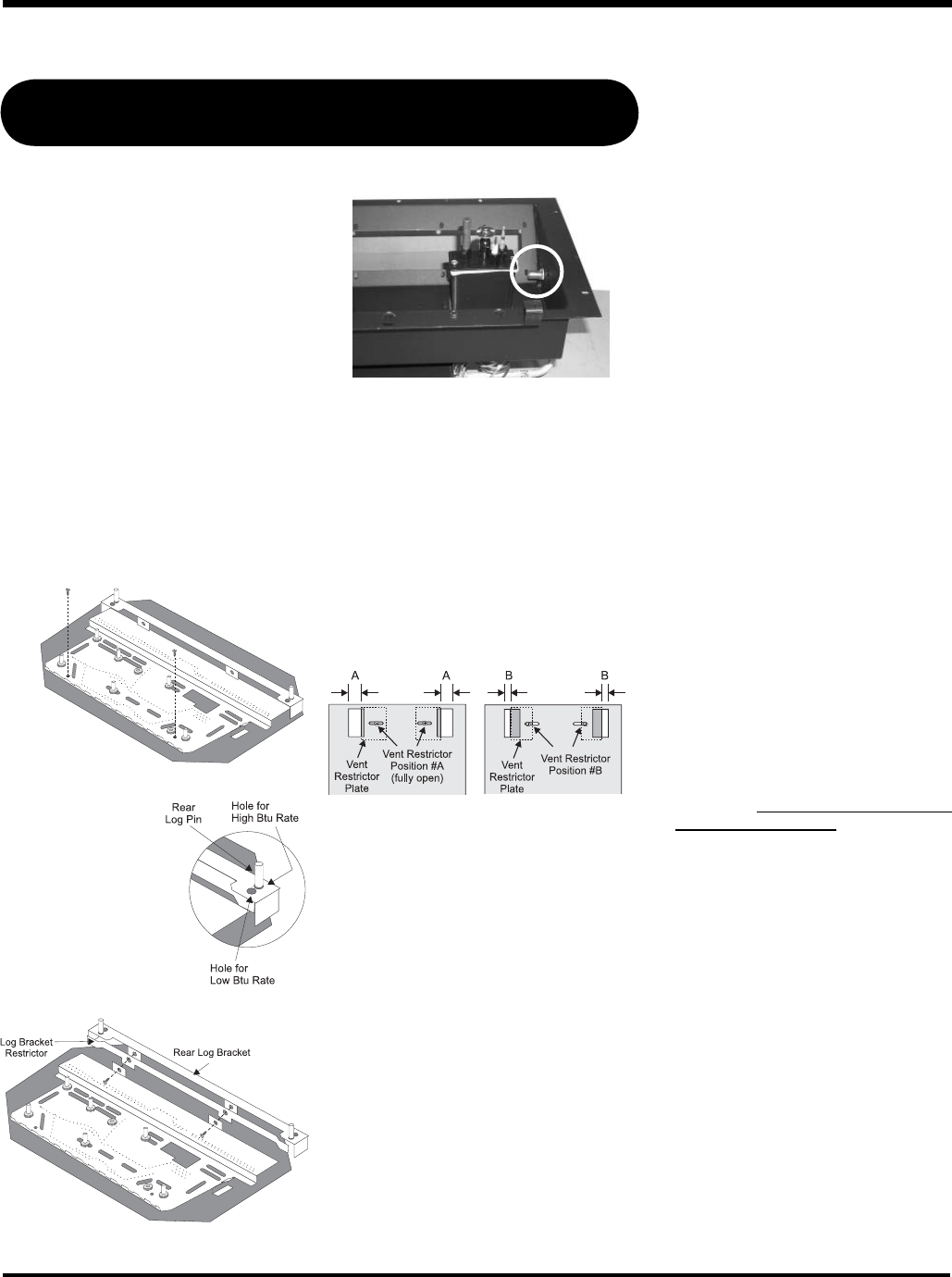
4) Unscrew the 2 Rear
Log Pins and move
to the front hole
position.
5) Remove Rear Log
Bracket and slide
the Log Bracket
Restrictor between
the Rear Log Bracket
Position the Log Bracket Restrictor between
the Rear Log Bracket and the burner.
6) Remove burner orifi ce with a 1/2" wrench
and discard.
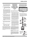
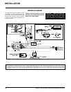
The manifold pressure is controlled by a regulator
built into the gas control, and should be checked
at the pressure test point.
Note: To properly check gas pressure, both
inlet and manifold pressures should
be checked using the valve pressure
ports on the valve.
1) Make sure the valve is in the "OFF"
position.
2) Loosen the "IN" and/or "OUT" pressure
tap(s), turning counterclockwise with a 1/8"
wide fl at screwdriver.
3) Attach manometer to "IN" and/or "OUT"
pressure tap(s) using a 5/16" ID hose.
4) Light the pilot and turn the valve to "ON"
position. Read manometer.
5) The pressure check should be carried out
with the unit burning and the setting should
be within the limits specifi ed on the safety
label.
6) When fi nished reading manometer, turn
off the gas valve, disconnect the hose and
tighten the screw (clockwise) with a 1/8" fl at
screwdriver. Note: Screw should be snug,
but do not over tighten
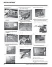
7) Reinstall new burner orifi ce (NG stamped
#37 or LP stamped #52) and tighten.
8) Reverse steps 3) and 2).
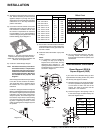
9) Adjust Vent restrictor setting: To set the
Vent restriction as indicated in the diagram,
simply loosen the screws and push the vent
restrictor plate to the correct position. Tighten
the screws.
Unit Btu/h Restrictor Opening
U39 38,000 A 1-3/4" (44mm)
30,000 B 1-1/4" (32mm)
Note: Use a
magnetic type
screwdriver if
possible.
and the burner, secure with the 2 screws.
Vent Restrictor set-
ting at High Btu/h
Vent Restrictor set-
ting at Low Btu/h
10) Attach the label "This unit has been
converted to..." on top of the Serial # decal
over the higher Btu information.
11) Check for gas leaks.
12) Check inlet and outlet pressures.
13) Check operation of fl ame control. Check
for proper fl ame appearance and glow on
logs.
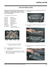
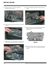
INSTALLATION