


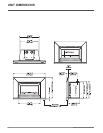
14 U32S-5 FPI Direct Vent Gas Insert
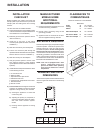
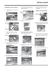
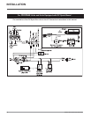
The remote control kit comes with a hand held transmitter, a receiver and
a wall mounting plate.
1) Choose a convenient location on the wall to install the receiver and
the receptacle box (protection from extreme heat is very important).
Run wires from the fi replace to that location. Use Thermostat Wire
Table.
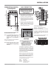
2) Connect the wires as per the wiring diagrams in this manual.
CAUTION
Do not connect the millivolt
remote control
the 120V wires.
3) Install 3 AAA alkaline batteries in transmitter and 4 AA alkaline bat-
teries in the receiver. Install the receiver and its cover in the wall.
Switch the remote receiver to "remote" mode. The remote control is
now ready for operation.
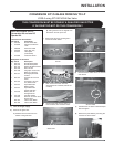
FINAL CHECK
Before leaving this unit with the customer, the installer must ensure that
the appliance is fi ring correctly. This includes:
1) Clocking the appliance to ensure the correct fi ring rate (rate noted
on label) at 15 minutes.
2) If required, adjusting the primary air to ensure that the fl ame does
not carbon. First allow the unit to burn for 15 min. to stabilize.
3) Check for proper draft.
CAUTION
Any alteration to the product that causes sooting
or carboning that results in damage to the exterior
facia is not the responsibility of the manufacturer.
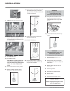
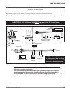
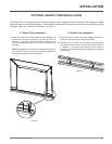
OPTIONAL WALL THERMOSTAT
A wall thermostat may be installed if desired, follow the wiring diagram
below. FPI offers an optional programmable thermostat but any 250-
750 millivolt rated non-anticipator type thermostat that is CSA, ULC or
UL approved may be used.
CAUTION
Do not connect the millivolt wall thermostat wires
to the 120V wires.
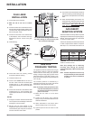
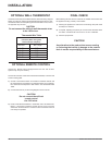
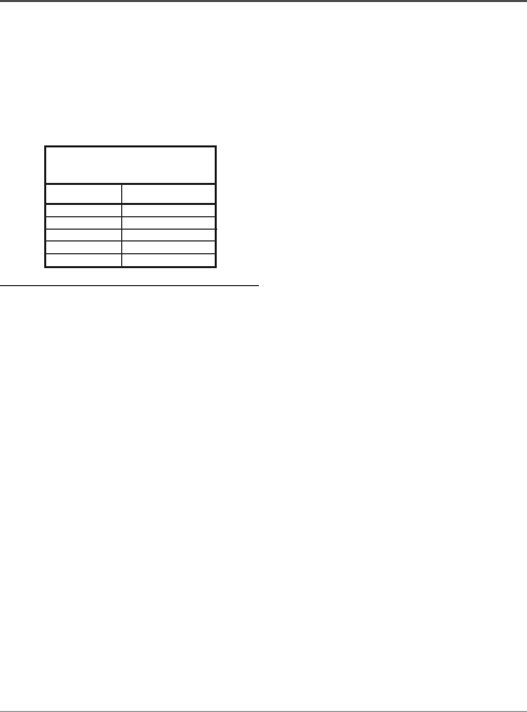
14 GA.
16 GA.
18 GA.
20 GA.
22 GA.
50 Ft.
32 Ft.
20 Ft.
12 Ft.
9 Ft.
Recommended Maximum Lead Length
(Two-Wire) When Using Wall
Thermostat (CP-2 System)
Wire Size Max. Length
Thermostat Wire Table
OPTIONAL REMOTE CONTROL
Use the FPI Remote Control Kit approved for this unit. Use of other
systems may void your warranty.
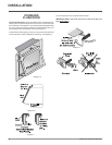
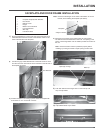
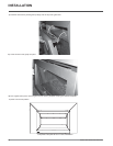
INSTALLATION