


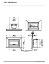

10 U32S-5 FPI Direct Vent Gas Insert
GAS PIPE
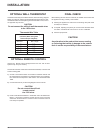
PRESSURE TESTING
The appliance must be isolated from the gas
supply piping system by closing its individual
manual shut-off valve during any pressure
testing of the gas supply piping system at test
pressures equal to or less than 1/2 psig. (3.45
kPa). Disconnect piping from valve at pressures
over 1/2 psig.
The manifold pressure is controlled by a
regulator built into the gas control, and should
be checked at the pressure test point.
Note: To properly check gas pressure, both
inlet and manifold pressures should
be checked using the valve pressure
ports on the valve.
1) Make sure the valve is in the "OFF"
position.
2) Loosen the "IN" and/or "OUT" pressure
tap(s), turning counterclockwise with a 1/8"
wide fl at screwdriver.
3) Attach manometer to "IN" and/or "OUT"
pressure tap(s) using a 5/16" ID hose.
4) Light the pilot and turn the valve to "ON"
position.
INSTALLATION
5) The pressure check should be carried out
with the unit burning and the setting should
be within the limits specifi ed on the safety
label.
6) When fi nished reading manometer, turn
off the gas valve, disconnect the hose and
tighten the screw (clockwise) with a 1/8"
fl at screwdriver. Note: Screw should be
snug, but do not over tighten.
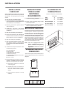
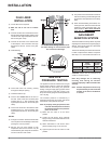
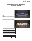
GAS INSERT
AERATION SYSTEM
The burner aeration is factory set but may need
adjusting due to either the local gas suppply or
altitude. Open the air shutter for a blue fl ame
or close for a yellow fl ame.
The burner assembly will need to be removed
in order to adjust burner aeration if required.
See steps 1-4 in 'Conversion from NG to LP.
Minimum Air shutter Opening
Glass
Crystals
Ceramic
Stones
Natural Gas 3/8" 1/8"
Propane 1/2" 3/8"
CAUTION: Carbon will be produced if air
shutter is closed too much.
Note: Any damage due to carboning
resulting from setting the aeration
controls improperly is NOT covered under
warranty.
Note: Aeration Adjustment should only
be performed by an authorized FPI
Installer at the time of installation
or service.
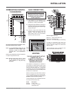
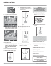
Be careful not to damage thermal insula-
tion when sliding on vent connector plate.
This could cause blockage.
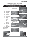
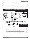
FLUE LINER
INSTALLATION
1) Cut the fl ex liner as required.
2) Mark the end of one liner to indicate
Inlet.
3) Connect the other end of the above liner to
the inlet side of the termination adaptor, seal
connection with high temperature silicone.
Secure with gear clamp.
4) Connect the 2nd liner to the exhaust side
of the adaptor, seal connection with high
temperature silicone. Secure with gear
clamp.
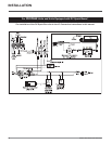
5) Install fl ashing.
6) Insert both liners into chimney, passing
through the damper opening.
7) Install termination cap.
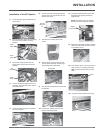
8) Connect the marked end of the liner to
the inlet collar of the vent connector plate
marked with an "I", seal connection with
high temperature silicone. Secure with gear
clamp.
9) Connect the 2nd liner to the exhaust collar
marked with an "E", seal connection with
high temperature silicone. Secure with gear
clamp.
NOTES:
1) Final gas connection should be made after
unit is in place to avoid damage to line when
pushing the unit into position.
2) Mill-pac may be used instead of high
temperature silicone and screws may be
used instead of gear clamps at connections
of liner to inlet and vent collars.