


Regency
®
P42-4 Zero Clearance Direct Vent Gas Fireplace
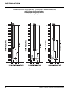
24
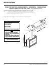
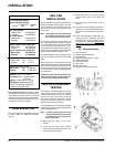
GAS LINE
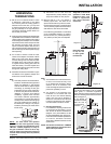
INSTALLATION
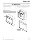
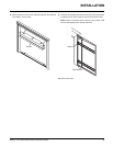
The gas line can be brought through either the
right or the left side of the appliance. The gas
valve is situated on the right hand side of the
unit and the gas inlet is on the right hand side
of the valve.
Note: If the gas line is being installed from
the left side, be sure to leave room to
accommodate servicing of the fan.
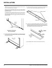
The gas line connection may be made of rigid
pipe, copper pipe or an approved fl ex connector.
(If you are using rigid pipe, ensure that the valve
can be removed for servicing.) Since some
municipalities have additional local codes it is
always best to consult with your local authorities
and the CAN/CGA B149 installation code.
For USA installations follow local codes and/or
the current National Fuel Gas Code, ANSI
Z223.1.
When using copper or fl ex connectors use only
approved fi ttings. Always provide a union so that
gas lines can be easily disconnected for burner
or fan servicing. Flare nuts for copper lines and
fl ex connectors are usually considered to meet
this requirement.
Important: Always check for gas leaks with a
soap and water solution or gas leak detector.
Do not use open fl ame for leak testing.
GAS PIPE PRESSURE
TESTING
The appliance must be isolated from the gas
supply piping system by closing its individual
manual shut-off valve during any pressure
testing of the gas supply piping system at
test pressures equal to or less than 1/2 psig.
(3.45 kPa). Disconnect piping from valve at
pressures over 1/2 psig (3.45 kPa).
The manifold pressure is controlled by a regulator
built into the gas control, and should be checked
at the pressure test point.
Note: To properly check gas pressure, both
inlet and manifold pressures should
be checked using the valve pressure
ports on the valve.
1) Make sure the valve is in the "OFF"
position.
2) Loosen the "IN" and/or "OUT" pressure
tap(s), turning counterclockwise with a 1/8"
(3mm) wide fl at screwdriver.
Note: Output capacity. The effi ciency rating
of the appliance is a product thermal effi ciency
rating determined under continuous operating
conditions and was determined independently
of any installed system. Vent height may or may
not change your effi ciency ratings.
HIGH ELEVATION
This unit is approved in Canada for altitude 0
to 4500 ft. (CAN1 2.17-M90) with the orifi ce
supplied.
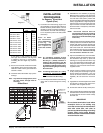
System Data
For 0 to 4500 feet altitude
Burner Inlet Orifi ce Sizes:
Natural Gas Propane
Burner #33 #50
Max. Input Rating
- Natural Gas 35,000 Btu/h
- Propane 35,000 Btu/h
Min. Input Rating
-Natural Gas 17500 Btu/h
-Propane 17500 Btu/h
Output Capacity with blower Off
Natural Gas 25,725 Btu/h
Propane 26,740 Btu/h
Output Capacity with blower On
Natural Gas 26,250 Btu/h
Propane 27,300 Btu/h
Supply Pressure
Natural Gas min. 5.0" w.c.
Propane min. 11.0" w.c.
Manifold Pressure (High)
Natural Gas 3.8" +/- 0.2" w.c.
Propane 10" +/- 0.2" w.c.
Electrical: 120 V A.C. System.
Circulation Fan: variable speed
130 CFM.
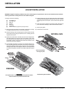
Log Set: Ceramic fi bre, 3 per set.
Vent System: Simpson
Dura-Vent
Direct Vent System
or Regency
®
Direct Vent System (Flex)
3) Attach manometer to "IN" and/or "OUT"
pressure tap(s) using a 5/16" (8mm) ID
hose.
4) Light the pilot and turn the valve to "ON"
position.
5) The pressure check should be carried out
with the unit burning and the setting should
be within the limits specifi ed on the safety
label.
6) When fi nished reading manometer, turn
off the gas valve, disconnect the hose
and tighten the screw (clockwise) with a
1/8"(3mm) fl at screwdriver. Note: Screw
should be snug, but do not over
tighten.
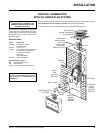
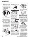
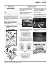
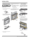
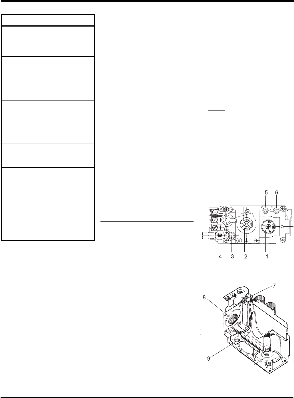
S.I.T. Valve Description
1) Gas on/off knob
2) Manual high/low adjustment
3) Pilot Adjustment
4) Thermocouple Connection - option
5) Outlet Pressure Tap
6) Inlet Pressure Tap
7) Pilot Outlet
8) Main Gas Outlet
9) Alternative TC Connection Point
INSTALLATION