


Regency P33-3 Zero Clearance Direct Vent Gas Fireplace
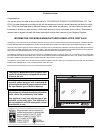
The Top Facing Support, the Side Nailing Strips
and the 2 Top Standoffs must be correctly po-
sitioned and attached to the top before the unit
is put into position.
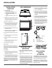
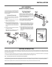
Top Standoff Assembly
The top standoffs are shipped in a fl at position
and must be pulled up and bent into the cor-
rect shape.
1) Remove the standoffs from on top of the
fi rebox by undoing the screws.
2) Take each standoff and bend into the cor-
rect shape. Bend up at the bend lines until
the screw holes in the standoff and the
pre-punched screw holes on the fi rebox top
line-up.
3) Attach the standoffs securely to the top with
4 screws per standoff.
Note: Secure the standoffs to the holes
closest to the edge of the fi rebox top.
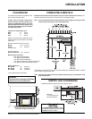
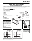
Top Facing Support &
Side Nailing Strips
Determine the total thickness of facing mate-
rial (e.g. drywall plus ceramic tiles) to allow the
fi nished surface to be fl ush with the front of the
unit. Total facing thickness can vary from 1/2"
(13mm) to 1-1/4" (32mm) thick.
The Top Facing Support & Side Nailing Strips
can be mounted in various positions depending
on the thickness of the facing material.
1) Mount Top Facing Support using the 3
supplied screws into the three pre-punched
screw holes on the top front of the unit. Adjust
support to desired facing material depth.
2) Mount Side Nailing Strip using the 3 sup-
plied screws into the three pre-punched
screw holes at the front sides of the unit.
Adjust support to desired facing material
thickness.
UNIT ASSEMBLY
PRIOR TO INSTALLATION
INSTALLATION
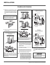
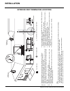
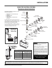
VENTING INTRODUCTION
The P33-3 uses the "balanced fl ue" technology Co Axial system. The inner liner vents products of combustion to the outside while the outer
liner draws outside combustion air into the combustion chamber thereby eliminating the need to use heated room air for combustion and losing
warm room air up the chimney.
There are 2 vent systems approved for use with the P33-3: the Regency Direct Vent System (Flex) for Horizontal Terminations only (see pages
11-12), and the Simpson Dura-Vent Systems for Horizontal and Vertical Terminations (see pages 13-24).
Note: These fl ue pipes must not be connected to any other appliance.
The gas appliance and vent system must be vented directly to the outside of the building, and never be attached to a chimney serving a separate solid
fuel or gas burning appliance. Each direct vent gas appliance must use it's own separate vent system. Common vent systems are prohibited.
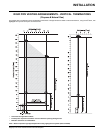
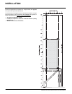
NOTE: Ensure compliance with the outside vent terminal location before cutting hole as both dimensions must be met.
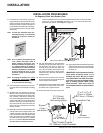
For a facing material depth of
1-1/4"(32mm), the top facing
support must be reversed.