


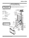

Regency P33-3 Zero Clearance Direct Vent Gas Fireplace
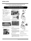
GAS PIPE PRESSURE
TESTING
The appliance must be isolated from the gas
supply piping system by closing its individual
manual shut-off valve during any pressure
testing of the gas supply piping system at
test pressures equal to or less than 1/2 psig.
(3.45 kPa). Disconnect piping from valve at
pressures over 1/2 psig.
The manifold pressure is controlled by a regu-
lator built into the gas control, and should be
checked at the pressure test point.
Note: To properly check gas pressure, both
inlet and manifold pressures should
be checked using the valve pressure
ports on the valve.
1) Make sure the valve is in the "OFF" posi-
tion.
2) Loosen the "IN" and/or "OUT" pressure
tap(s), turning counterclockwise with a 1/8"
wide fl at screwdriver.
3) Attach manometer to "IN" and/or "OUT"
pressure tap(s) using a 5/16" ID hose.
4) Light the pilot and turn the valve to "ON"
position.
5) The pressure check should be carried out
with the unit burning and the setting should
be within the limits specifi ed on the safety
label.
6) When fi nished reading manometer, turn
off the gas valve, disconnect the hose and
tighten the screw (clockwise) with a 1/8"
fl at screwdriver. Note: Screw should be
snug, but do not over tighten.
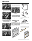
INSTALLATION
Incorrect fl ame pattern will have small, prob-
ably yellow fl ames, not coming into proper
contact with the rear burner or thermopile
or thermocouple.
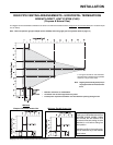
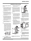
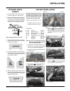
HIGH ELEVATION
This unit is approved in Canada for altitude
to 4500 ft. (CAN/CGA-2.17-M91). For Natural
Gas installations above 4500 ft. follow current
CAN/CGA-B149.1.
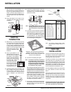
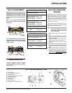
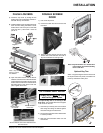
S.I.T. VALVE DESCRIPTION
1) Gas cock knob
2) Manual high/low adjustment
3) Pilot Adjustment
4) Thermocouple Connection - option
5) Outlet Pressure Tap
6) Inlet Pressure Tap
7) Pilot Outlet
8) Main Gas Outlet
9) Alternative TC Connection Point
PILOT ADJUSTMENT
Periodically check the pilot fl ames. Correct
fl ame pattern has three strong blue fl ames:
1 fl owing around the thermopile, 1 around
the thermocouple and 1 fl owing across the
burner (it does not have to be touching the
burner).
Note: If you have an incorrect fl ame pat-
tern, contact your Regency dealer for further
instructions.
P33-NG3 System Data
Conversion Kit# 431-969
For 0 to 2000 feet altitude
Burner Inlet Orifi ce Sizes: # 4 4
Max. Input Rating 22,500 Btu/h
Min. Input Rating 12,500 Btu/h
For 2000 to 4500 feet altitude
Burner Inlet Orifi ce Sizes: # 4 5
Max. Input Rating 21,000 Btu/h
Min. Input Rating 10,500 Btu/h
Supply Pressure min.5.0" w.c.
Manifold Pressure
(High) 3.8"+/- 0.2" w.c.
P33-LG3 System Data
For 0 to 4500 feet altitude
Burner Inlet Orifi ce Sizes: #54
Max. Input Rating 21,500 Btu/h
Min. Input Rating 10,500 Btu/h
Supply Pressure min.12.0" w.c.
Manifold Pressure
(High) 11"+/- 0.2"w.c.