


Regency P121/P121LC/P121RC/P131 Zero Clearance Room Sealed Gas Fireplace
28
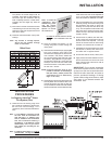
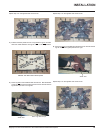
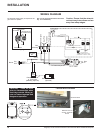
WIRING DIAGRAM
Caution: Ensure that the wires do
not touch any hot surfaces and are
away from sharp edges.
CAUTION: Label all wires
prior to disconnection when
servicing controls. Wiring er-
rors can cause improper and
dangerous operation.
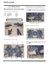
INSTALLATION
No electrical power supply is required for the
gas control to operate.
(Do not cut the ground terminal off under
any circumstances.)
Terminal Block Location
Terminal Block
Remove cover to
access Terminal
Block
FROM
POWER LIVE
POWER NEUTRAL
WHITE
TERMINAL
BLOCK
FAN1
1
2
FAN2
~
BLACK
GROUND
(WIRE SUPPLY & INSTALLBY OTHERS)
910-802 BLACK
CONVECTIONAIR
TEMPERATURE SWITCH
(THERMO DISC - NORMALLY OPEN)
~
ON-OFF SWITCH
(910-138) BLACK
910-610 BLACK
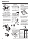
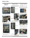
Lockwasher
Nut
#8 Ground Lug
(for mobile home)
Star washer
Ground Wire
Grounding Lug Detail
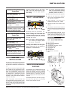
Yellow
Orange
Burner
ON
OFF
DC Spark
Box
Ground
To Thermocouple IN
Pilot
Assembly
H
I
L
O
O
F
F
O
N
P
I
L
O
T
Gas Pilot
Thermopile
Thermocouple
Electrode
Remote Transmitter
(Optional)
ON OFF
Regency
Remote Receiver
or Thermostat
(Millivolt) (Optional)
Brown
White
"S.I.T" Valve
(To THTP)
(To TH)
Gas
In