


Regency P121/P121LC/P121RC/P131 Zero Clearance Room Sealed Gas Fireplace 23
INSTALLATION
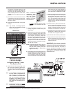
GAS PIPE PRESSURE
TESTING
The appliance must be isolated from the gas
supply piping system by closing its individual
manual shut-off valve during any pressure
testing of the gas supply piping system at test
pressures equal to or less than 3.45 kPa.
Disconnect piping from valve at pressures over
3.45 kPa.
The manifold pressure is controlled by a regu-
lator built into the gas control, and should be
checked at the pressure test point.
Note: To properly check gas pressure,
both inlet and manifold pressures
should be checked using the valve
pressure ports on the valve.
1) Make sure the valve is in the "OFF" position.
2) Loosen the "IN" and/or "OUT" pressure
tap(s), turning counterclockwise with a
1/8" wide flat screwdriver.
3) Attach manometer to "IN" and/or "OUT"
pressure tap(s) using a 5/16" ID hose.
4) Light the pilot and turn the valve to "ON"
position.
5) The pressure check should be carried out
with the unit burning and the setting should
be within the limits specified on the safety
label.
6) When finished reading manometer, turn off
the gas valve, disconnect the hose and
tighten the screw (clockwise) with a 1/8"
flat screwdriver.
Note: Screw should be
snug, but do not over tighten.
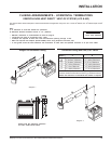
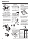
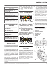
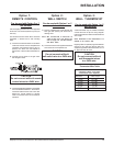
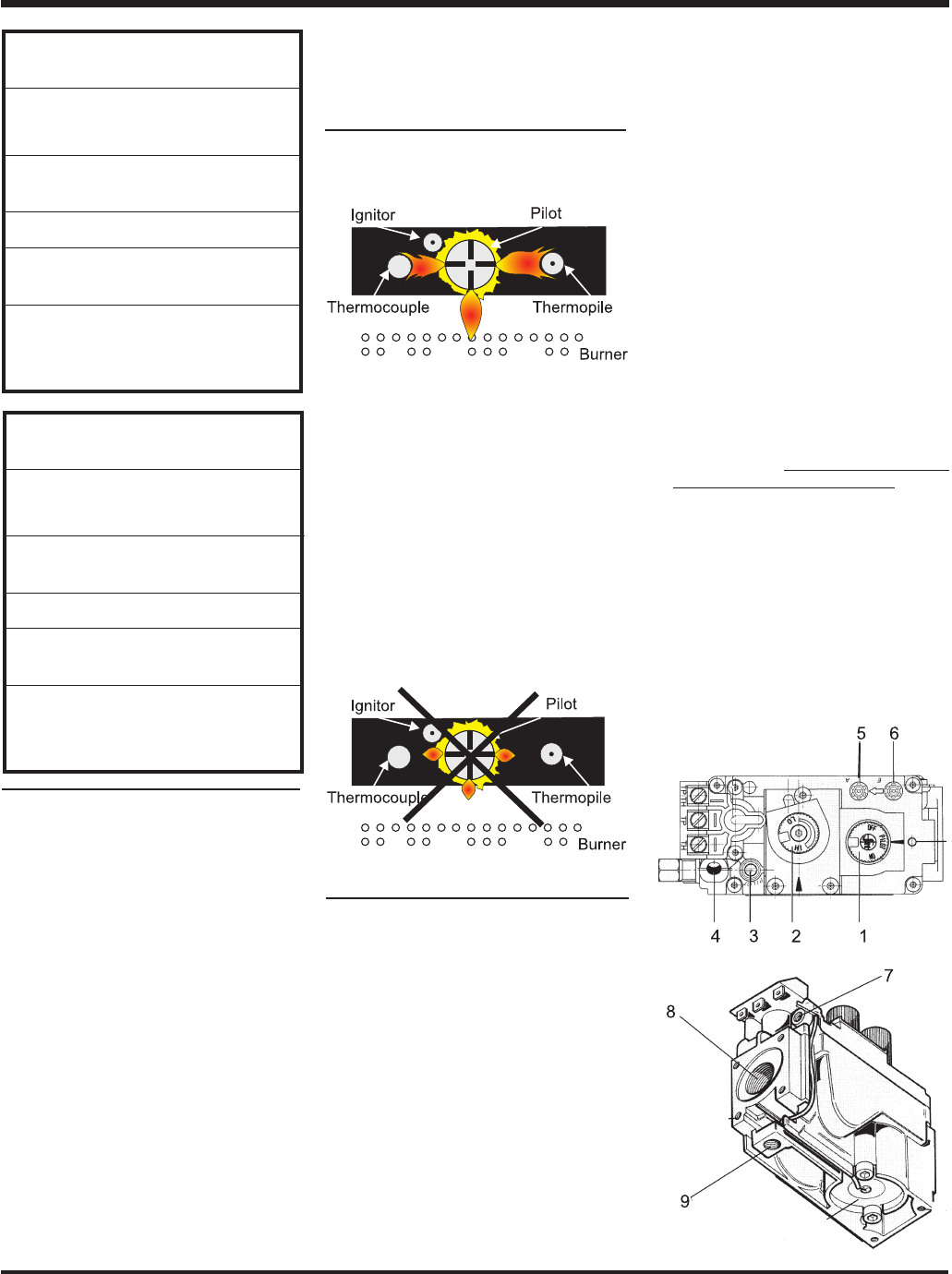
S.I.T. VALVE DESCRIPTION
1) Gas cock knob
2) Manual high/low adjustment
3) Pilot Adjustment
4) Thermocouple Connection - option
5) Outlet Pressure Tap
6) Inlet Pressure Tap
7) Pilot Outlet
8) Main Gas Outlet
9) Alternative TC Connection
Point
Important: Always check for gas leaks
with a soap and water solution or gas
leak detector. Do not use open flame for
leak testing.
P121/P121LC/P121RC/P131-NG
System Data
For 0 to 4500 feet altitude
Burner Inlet Orifice Sizes: #31
Pilot Orifice NG
Max. Input Rating 42 mj.
Min. Input Rating 22 mj.
Supply Pressure min. 1.13 kPa
Manifold Pressure
(High) 1.00 kPa
Log Set: Ceramic fibre, 8 per set.
Flue System: Regency Astrocap
TM
, Re-
gency Direct Vent System (Flex) and Simp-
son Dura-Vent Direct Flue System
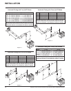
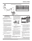
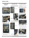
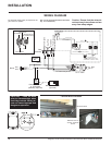
GAS LINE
INSTALLATION
The gas line can be brought through either the
right, the left side or the bottom of the appliance.
The gas valve is situated on the bottom of the
unit.
The gas line connection may be made of rigid
pipe, copper pipe or an approved flex connec-
tor. (If you are using rigid pipe, ensure that the
valve can be removed for servicing.) Since
some municipalities have additional local codes
it is always best to consult with your local
authorities and AS5601-2004 (Australian
Installation Code) NZS 5261(New Zealand
Installation Standard).
When using copper or flex connectors use
only approved fittings. Always provide a union
so that gas lines can be easily disconnected for
servicing. Flare nuts for copper lines and flex
connectors are usually considered to meet this
requirement.
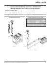
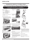
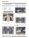
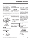
Periodically check the pilot flames. Cor-
rect flame pattern has three strong blue
flames: 1 flowing around the thermopile,
1 around the thermocouple and 1 flowing
across the burner (it does not have to be
touching the burner).
Note: If you have an incorrect flame pat-
tern, contact your Regency dealer
for further instructions.
Incorrect flame pattern will have small,
probably yellow flames, not coming into
proper contact with the rear burner or
thermopile or thermocouple.
P121/P121LC/P121RC/P131-LPG
System Data
For 0 to 4500 feet altitude
Burner Inlet Orifice Sizes: #50
Pilot Orifice LPG
Max. Input Rating 41 mj.
Min. Input Rating 22 mj.
Supply Pressure min. 3.00 kPa
Manifold Pressure
(High) 2.65 kPa
Log Set: Ceramic fibre, 8 per set.
Flue System: Regency Astrocap
TM
, Re-
gency Direct Vent System (Flex) and Simp-
son Dura-Vent Direct Flue System
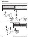
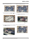
PILOT ADJUSTMENT