


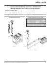
Regency P121/P121LC/P121RC/P131 Zero Clearance Room Sealed Gas Fireplace
12
INSTALLATION
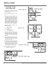
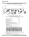
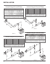
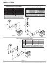
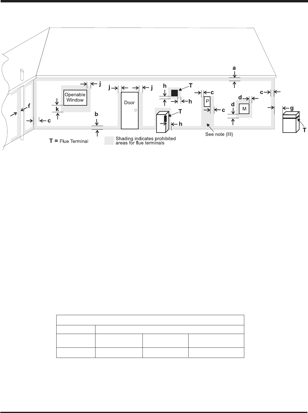
EXTERIOR FLUE TERMINATION LOCATIONS
Minimum clearances required for balanced flue terminals or
the flue terminals of outdoor appliances
according to AS5601-2004 (AGA gas installation code) or NZS 5261 (New Zealand)
Minimum
Clearance (mm)
a Below eaves, balconies or other projections:
- Appliances up to 50 MJ/h input 300
- Appliances over 50 MJ/h input 500
b From the ground or above a balcony 300
c From a return wall or external corner 500
d From a gas meter (M) 1000
e From an electricity meter or fuse box (P) 500
f From a drain or soil pipe 150
g Horizontal from any building structure (unless appliance is approved
for closer installation) or obstruction facing a terminal 500
h From any other flue terminal, cowl or combustion air intake 500
j Horizontally from an openable window, door, or non-mechanical air inlet, or
any other opening into a building, with the exception of sub-floor ventilation
(see also Note (I)):
- Appliances up to 150 MJ/h input 500
- Appliances over 150 MJ/h input 1500
k Vertically below an openable window, door, or non-mechanical air inlet,
or any other opening into a building, with the exception of sub-floor ventilation
(see also Note (I)): see table below
Clearance 'k' in mm
Space Heaters All Other Appliances
Up to 50 MJ/h Up to 50 MJ/h input Over 50 MJ/h input Over 150 MJ/h input
input to 150 MJ/h input
150 500 1000 1500
NOTES:
(I) For mechanical air inlets, including spa blowers, the clearance 'j' and 'k' shall be 1500 mm in all cases.
(II) All distances shall be measured vertically or horizontally along the wall to a point in line with the nearest
par to of the terminal.
(III) Prohibited area below electricity meter or fuse box extends to ground level.
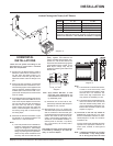
(IV)A flue terminal of this type shall not be located under a roofed area unless the roofed area is fully open on
at least two sides and a free flow of air at the appliance is achieved.