


21
E33 FPI Direct Vent Gas Insert
MAINTENANCE
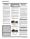
FAN MAINTENANCE
If your fan requires maintenance or replace-
ment, access to the fan is through the plate on
the fl oor of the fi rebox. NOTE: the unit MUST
NOT be operated without the fan access
panel securely in place.
Caution: Label all wires prior to discon-
necting when servicing controls. Wiring
errors can cause improper and danger-
ous operation. Verify proper operation
after servicing.
DOOR GLASS
Your FPI stove is supplied with high temperature,
5 mm Neoceram ceramic glass that will withstand
the highest heat that your unit will produce. Do
not abuse the glass by striking the surface or
by slamming the door shut.
If your glass requires cleaning, we recommend
using an approved glass cleaner available at all
authorized dealers. Do not use abrasive mate-
rials. Do not clean the glass when hot.
In the event that you break your glass by impact,
purchase your replacement from an authorized
FPI dealer only, do not use substitute materials.
Follow our step-by-step instructions for replace-
ment. Warning: Wear gloves when removing
damaged or broken glass.
Caution: Do not operate appliance with
glass panels removed, cracked or broken.
Replacement of the glass should be done by
a licensed or qualifi ed service person.
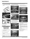
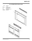
Flush Glass Replacement
Remove the fl ush door front (refer to page 14).
Remove the 4 glass clips from each corner.
Slide in the new replacement glass. Push the
4 glass clips back onto the frame.
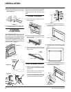
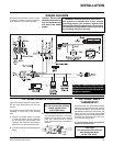
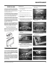
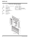
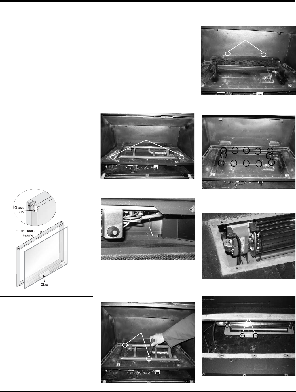
To Remove Fan:
1) Turn the unit off and allow it to cool down to
room temperature.
2) Unplug or disconnect power source to
stove.
3) Remove the fl ush door (refer to p.14).
4) Remove logs and grate (refer to p.10).
5) Remove optional brick panel set, if installed
(refer to page 9).
6) Remove base brick set. (When removing
base brick sides the two screws that hold
the grate down must be removed fi rst).
Straighten adjustment wire.
Air Shutter Wire
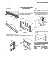
9) Remove the rear log support by unscrewing
the 2 screws.
8) Remove the Burner by removing the 2
screws (1 on burner bracket and one on
valve tray). Tilt up the left burner and slide
to the left away from the orifi ce.
10) Remove the 12 screws holding the Access
Panel in place.
Fan Access Plate Screws
Screws
11) Unplug the wires from the fan motor (from
inside the stove).
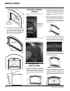
7) Straighten the adjustment wire under the
fi rebox base.
Screws
12) Remove the 2 screws from the fan
bracket.
Screws
Screws