


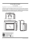
10 E33 FPI Direct Vent Gas Insert
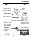
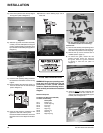
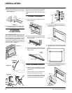
Top Bracket
5) Place the top bracket onto the top edge of
the top panel (refer to Diagram 2).
Diagram 2
6) Slide the top panel and bracket assembly
carefully onto the baffl e plate ensuring the
panel is centered. Make sure the tabs of the
top bracket fi t into the baffl e openings (refer to
Diagram 3).
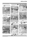
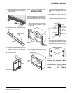
7) Insert the back panel by sliding it between
the sidewalls of the fi rebox and the rear log
support.
Diagram 3
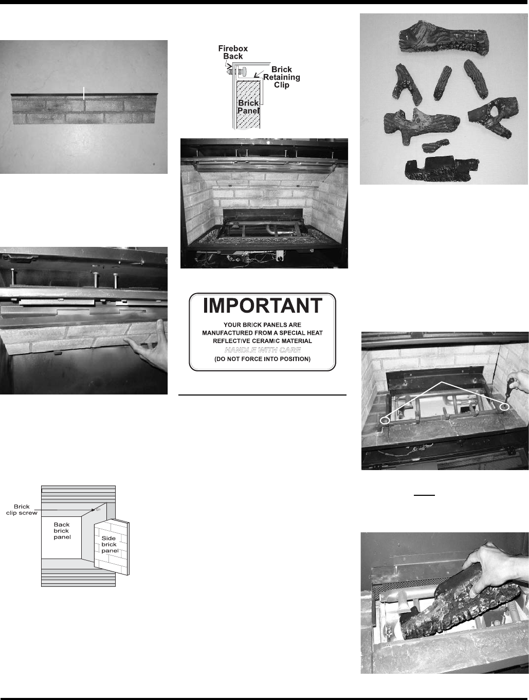
8) Before installing the side brick panels, re-
move the screws from the side brick clips
(refer to Diagram 4).
Diagram 4
9) Insert the side panel by positioning it fl at
against the side walls. Tilt the panel
towards the middle of the fi rebox, then insert
the bottom front corner. Repeat on the other
side.
10) Install the 2 brick retaining clips, one on
each side.
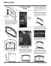
Final Installation
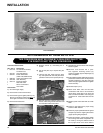
LOG INSTALLATION
WARNING: Dangerous operating condi-
tions may occur if these logs are not
positioned in their correct certifi ed
locations. Read the following instruc-
tions carefully and refer to the attached
diagram.
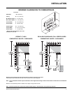
Materials Required:
Complete Log Set (Part # 340-930)
Contains the following:
Description
03-17 Bottom Log
03-18 Center Top Log
03-19 Front Log
03-20 Left Log
03-21 Right Log
03-22 Left top Log
03-23 Rear Log
03-24 Right Top Log
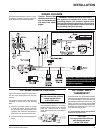
Diagram 2
03-17
The "03" reference numbers (i.e. 03-23)
are molded into the rear of each log.
03-17
03-20
03-23
03-21
03-22
03-24
03-18
03-19
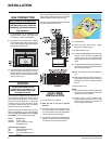
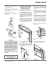
Instructions:
1) Remove and carefully unwrap the logs from
the box. Please handle with care and do not
force them into position to avoid chipping.
2) Remove the top louver and fl ush door if
installed (refer to page 14).
3) To remove the grate, loosen the two
Phillips screws which are securing
the grate. Slide the grate outwards
to remove it from the unit (refer to
Diagram 1).
Diagram 1
4) Angle log 03-17 and slide it between the
top and bottom burner tube under the “T”
section until it touches the left grate support
bracket (refer to Diagram 2).
INSTALLATION
Screws