


9
Regency E21 Gas Fireplace Insert
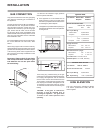
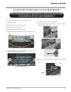
Note: Do not operate unit if fl ue connector is not
fastened in original position.
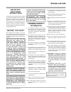
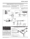
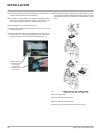
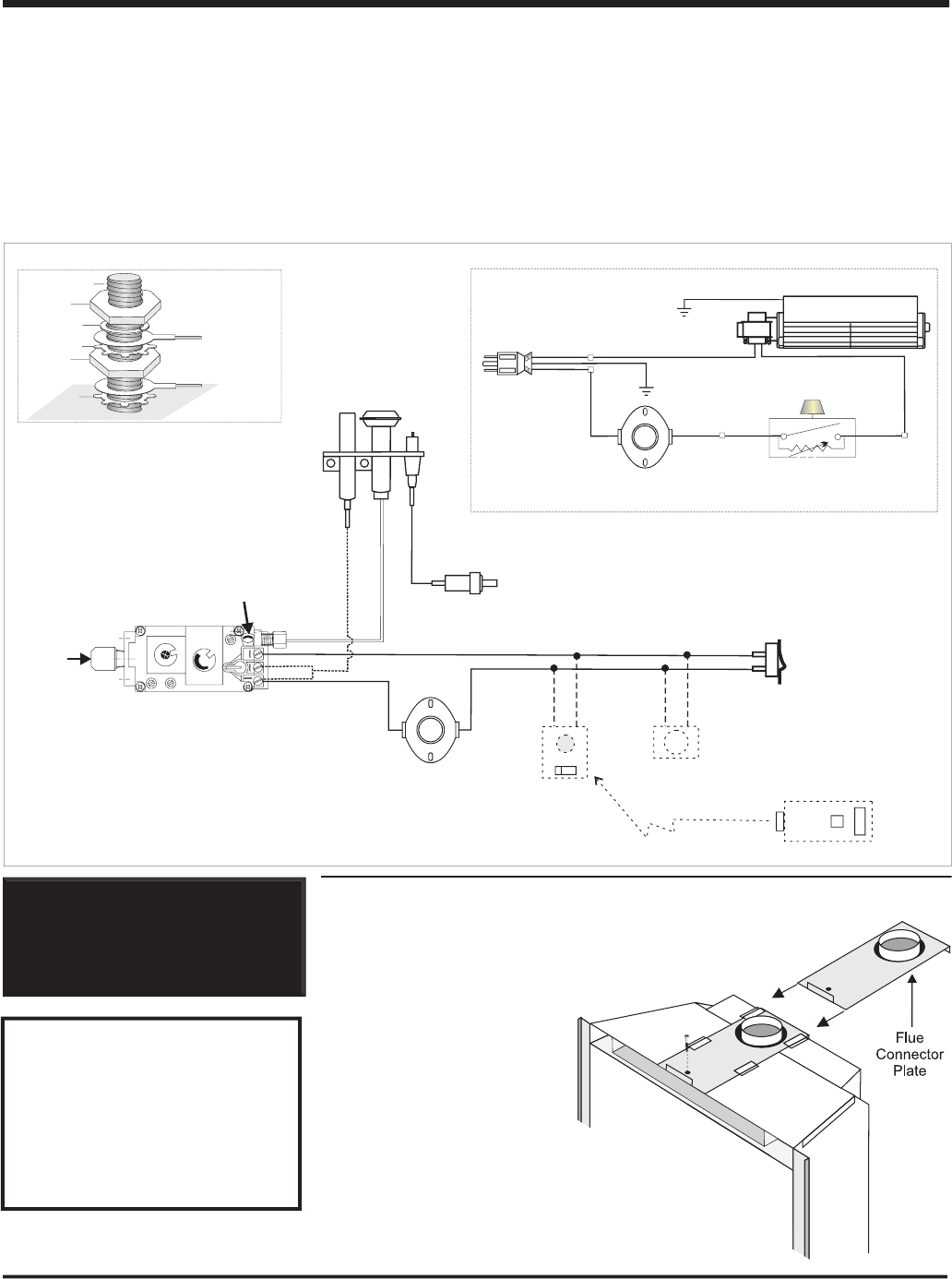
WIRING DIAGRAM FOR THE E21-NG1 AND E21-LP1
INSTALLATION
CAUTION: Label all wires prior
to disconnection when servicing
controls. Wiring errors can
cause improper and dangerous
operation.
WARNING: Electrical Grounding
Instructions
This appliance is equipped with a
three pronged (grounding) plug for
your protection against shock hazard
and should be plugged directly into
a properly grounded three-prong
receptacle. Do not cut or remove the
grounding prong from this plug.
This heater does not require a 120V A.C. supply
for operation. In case of a power failure, the
burner switch and the optional remote control/
thermostat will continue to operate. However,
a 120V A.C. power supply is needed for the
fan/blower operation.
Caution: Ensure that the wires do
not touch any hot surfaces and are
away from sharp edges.
When connected with 120 volts, the appliance
must be electrically grounded in accordance
with local codes or, in the absence of local
codes the current CSA C22.1 (in Canada) or
with the National Electrical Code ANSI/NFPA
70-1987 (in USA).
NOTE: This unit is equipped with a heat
sensor thermodisc which will
prevent the blower from operating
until the unit reaches the correct
temperature.
Green
Ground
Neutral
Live
Black
Black
Re
d
Black
Fan
Thermodisc
ON OFF
Rotary Speed
Control
120V AC
60 Hz
Ground
Fan
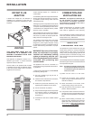
Grounding
Lug Detail
Lockwasher
Fanground
Powercord
groundwire
St
arwasher
Nut
Nut
#8GroundLug
St
arwasher
Gas
Pilot
Thermopile
Electrode
Gas
In
Piezo
Ignitor
Thermocouple
In
Brown
Re
d
White
Pilot
Assembly
"S.I.T" Valve
H
I
L
O
O
F
F
O
N
P
I
L
O
T
Vent Spill
Switch
(Auto Reset)
Burner
ON
OFF
Remote
Transmitter
(Optional)
Thermostat
(Millivolt)
(Optional)
Remote
Receiver
(Optional)
(Millivolt)
ONOFF
Regency
Black
Red
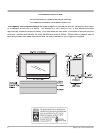
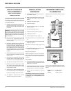
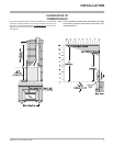
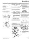
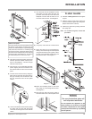
FLUE CONNECTOR INSTALLATION
1)
Remove the screw holding the fl ue connector
plate to the appliance.
2)
Slide the plate out and attach to
the fl ue liner inside the fi replace
to the fl ue collar with three sheet
metal screws.
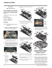
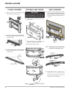
3)
Place the appliance on the hearth.
Push the appliance into the fi re-
place and at the same time slide the
plate back onto the appliance.
4)
Replace the screw holding the plate just
Replace the screw holding the plate just
before completely pushing the appliance into
the fi replace.