


5
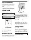
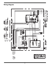
Connecting Power to the
Controller
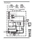
Supply power from the 120 VAC power input from the
heater to the controller power inputs Terminal Block
(TB1). This is accomplished by connecting wiring from
the control box to the heater TB1 board 120 VAC
power input connections. Refer to wiring diagrams.
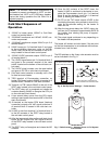
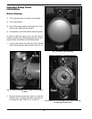
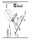
Fig. 3: Component Locations — Hi Delta
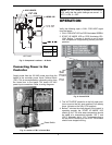
Fig. 4: Location of TB1 in Control Box
NOTE: If a “DIP” switch is provided on the control
PCB, verify that the switch settings are correct: 1 =
OFF, 2 = ON, 3 = OFF.
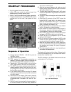
OPERATION
Verify the following upon a CALL FOR HEAT signal
from the heater:
1. CALL FOR HEAT LED on PCB illuminates GREEN.
2. START UP MODE LED on PCB illuminates YEL-
LOW. Before 7 minutes it should go out if boiler
inlet temperature is approaching the set point tem-
perature.
3. The “ACTUATOR” should be in the fully open posi-
tion or move to the fully open position if not already
there. (Actuator at the fully CCW position)
4. Before 7 minutes time has elapsed if the control is
operating properly the “START UP MODE” LED
should go out. The inlet water temperature should
be stable at a temperature between 105° F and
120° F (Normally set to 110° F) cooresponding to
the Set Point Pot setting on the PCB. The actuator
should have stopped moving.
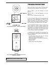
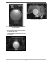
CALL FOR HEAT
START UP MODE
INLET TEMP ERROR
SENSOR OUT OF RANGE
Set
Point
Pot
Fig. 5: Control PCB
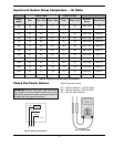
Models X
302B-902B
7.0″
992B-2342B
13.20″
LEFT SIDE
Reset Switch