


15
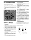
START-UP PROCEDURE
• Run full system flow for two minutes.
• Initiate PID pump control to achieve target inlet
temperature by slowing injector pump.
• Boiler ΔT will not increase during bypass operation.
• If target temperature is not achieved after seven
minutes from “call for heat”, the system will shut
down.
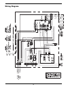
Sequence of Operation
1) Supply separate 220VAC, 1 Ø, 60 Hz power to
Cold Run control.
2) Call for heat occurs at heater.
3) TRIG terminal of Economaster connection on
heater CPW board outputs 24VAC to terminal 4 of
terminal block 3 located in Cold Run controller.
4) Terminal 4 of TB 3 sends 24VAC to the coil of the
SPST relay located in the cold run control panel.
5) The SPST relay coil is energized and closes the
contacts allowing 24VAC from the Cold Run con-
trol transformer to be sent to the CFH terminal of
the Cold Run circuit board.
a) A two second delay occurs from the CFH signal
waiting to send power from terminal MC of the cold
run circuit board.
6) J9 terminal on the heater CPW board (interlock
connection) outputs a 24 VAC signal to terminal 2
of terminal block 3 located in the cold run con-
troller.
7) 24 VAC is sent from terminal 2 of terminal block 3
to the NO contacts of the DPST relay located in
the cold run control panel.
8) After the two second delay on the cold run circuit
board, pin MC outputs a 24 VAC signal to terminal
AL0 of the Hitachi inverter.
9) The AL0 relay closes and outputs a 24 VAC signal
to the coil of the DPST relay located in the cold run
control panel.
10) The DPST relay coil energizes and closes the NO
contacts.
11) Once the NO contacts of the DPST close, the
heater 24 VAC is sent back to the heater to com-
plete the Economaster circuit (pin 3 of terminal
block 3) and the interlock circuit (pin 1 of terminal
block 3) allowing the heater to fire.
12) Pin SC of the cold run circuit board sends 24VAC
to Pin 1 (Forward) on Hitachi Inverter.
13) PCS terminal on Inverter outputs 12VDC signal to
the common terminal of the reset switch located
on the bottom of the cold run control panel.
14) The 12VDC signal crosses over the reset switch
and goes to Pin FS on cold run circuit board.
15) 12VDC on pin FS is jumpered to pin S1 on the
cold run circuit board.
16) Pin FR on the TVC board outputs 10VDC to the
Inverter to drive injector pump at full speed two-
minutes waiting for the heater to reach full fire.
17) After the two-minute delay the 10VDC output sig-
nal from pin FR reduces to approximately 8VDC at
the inverter thus slowing the pump to approxi-
mately 50 Hz.
18) The output signal continues to vary depending on
the heater inlet temperature.
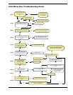
The heater will lockout and shut down if the set point
on the inlet temperature is not achieved within seven-
minutes from a call for heat.
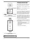
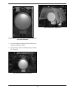
The DIP switches on the Hitachi Inverter must be set
as indicated on Fig. 19 below.
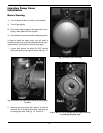
Fig. 18: Control Board
Fig. 19: DIP Switch Settings