


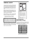

4
COLD WATER START
Before arriving at the job site to begin the installation,
it's important to first inspect the system and determine
what materials you will need. Some parts are includ-
ed with the controller while others you will need to
provide.
1 Control Box
1 Temperature Sensor
1 Valve assembly with actuator (Shipped separately)
Wiring and mounting hardware (Provided by installer)
INSTALLATION
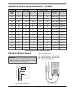
Check the Power Source
Check the power source:
AC = 108 VAC Minimum, 132 VAC MAX
AB = 108 VAC Minimum, 132 VAC MAX
BC = <1 VAC Maximum
Mounting the Control Box
The control box should be mounted on the side of the
heater to which the system piping and valve assembly
are to be attached. The controller should be mounted
so as to provide maximum support by using the
mounting holes provided on the base of the controller
to the side center brace on the heater. You will need to
drill mounting holes and holes through the heater side
panel for the routing of wiring and the sensor. A tem-
plate is supplied for field-installed kits to locate the
control box properly.
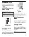
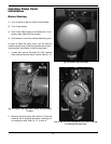
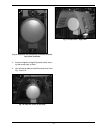
Attaching the Temperature
Sensor
Avoid routing wiring on or near other electrical wires,
conduit, motors, spark igniters or other sources of
high, intermittent voltage or current. The sensor should
be placed in the dry well on the inlet header. Ensure it
is installed using thermopaste (field supplied) and it is
held firmly at the bottom of the well.
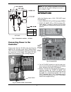
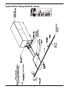
Connecting the Valve
Assembly
Connect valve assembly “T CONNECTION “ into the
piping with the actuator input wiring facing the heater
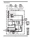
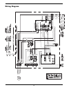
side panel, as shown below. Route wiring to the con-
trol thru the bottom panel knockouts to TB2. Refer to
the wiring diagram provided on the inside of control
cover assembly.
NOTE: Four knockouts are located on the bottom
of the control for ease of installation.
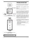
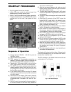
CIRCUIT
BREAKER
WHITE
GROUND
BLACK
GREEN
ABC
WARNING: Using a multi-meter, check the follow-
ing voltages at the circuit breaker panel prior to con-
necting any equipment. Make sure proper polarity is
followed and house ground is proven.
Fig. 1: Wiring Connections
Fig. 2: Multi-meter
CAUTION: Do not use for swimming pool applica-
tions