


10
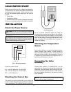
COLD WATER RUN
Purpose
The Cold Water Run system utilizes a variable-speed
pump to inject the proper amount of water from the
main system loop into the boiler to maintain the opti-
mum inlet temperature. This approach allows the full
capacity of the boiler to be utilized to meet the system
load, while at the same time continuously maintaining
the optimum inlet water temperature to prevent con-
densation.
Typical Cold Water Run
Applications
• Swimming pools.
• Snow melting.
• Low temperature radiant panel.
• Water source heat pumps.
• Any system with steady state return water temper-
ature below 105°F.
CWR vs. CWS
• Cold water start is for transient cold water opera-
tion.
• Cold water run is for continuous operation below
105°F system return temperature.
• Cold water start maintains design flow rate at sys-
tem design temperature but reduces bolier flow
rate during heavy by-pass operation.
• Cold water run maintains constant design flow rate
in the boiler.
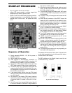
INSTALLATION
Before arriving at the job site to begin the installation,
it's important to first inspect the system and determine
what materials you will need. Some parts are includ-
ed with the controller while others you will need to
provide.
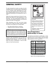
Installation Codes
Installations must be in accordance with local, state,
provincial, and national codes, laws, regulations and
ordinances. In the absence of local codes, installa-
tions must be in accordance with the latest editions of
the:
• National Fuel Gas Code, ANSI Z223.1/NFPA 54
• National Electrical Code, ANSI/NFPA 70
• For Canada only: CAN/CGA B149.1 installation
Code (B149.1) and CSA C22.1 C.E.C. Part 1 and
Part 2
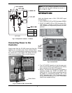
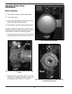
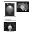
Mounting the Control Box
The control box should be mounted on the side of the
heater to which the system piping and pump assem-
blies are to be attached. The controller should be
mounted so as to provide maximum support by using
the mounting holes provided on the base of the con-
troller to the side center brace on the heater. You will
need to drill mounting holes and holes through the
heater side panel for the routing of wiring and the sen-
sor. A template is supplied for field-installed kits to
locate the control box properly.
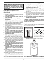
Indoor and Outdoor
Installations
The cold water run control panel is rated for indoor use
only. Do not mount or install the control panel in areas
where dripping, flooding, rain, snow or spraying water
may come in contact with the enclosure. If the injection
pump is located outdoors, the optional outdoor cover
must be installed according to the instructions in the
following section. For outdoor installations mount the
control panel indoors and route the wiring to the appro-
priate connection points. Wire length is not to exceed
25 feet in any one direction. Contact your local sales
representative for further information.
NOTE: The heater should not be located in an area
where possible water leakage will result in damage
to the area adjacent to the heater or to the structure.
When such locations cannot be avoided, it is rec-
ommended that a suitable drain pan, with adequate
drainage, be installed under the heater. The pan
must not restrict combustion air flow.
CAUTION: Remote mounted controller must be
installed within 25 feet of the heater.