


27
m
on venting system are located and other spaces
of the building. Turn on clothes dryers and any
appliance not connected to the common venting
system. Turn on any exhaust fans, such as range
h
oods and bathroom exhausts, so they will oper-
ate at maximum speed. Do not operate a summer
e
xhaust fan. Close fireplace dampers.
(d) Place in operation the appliance being inspected.
Follow the lighting instructions. Adjust thermostat
so appliance will operate continuously.
(e) After it has been determined that each appliance
remaining connected to the common venting sys-
tem properly vents when tested as outlined above,
return doors, windows, exhaust fans, fireplace
dampers and any other gas burning appliance to
their previous conditions of use.
(f) Any improper operation of the common venting
system should be corrected so that the installation
conforms with the latest edition of the National
Fuel Gas Code, ANSI Z223.1 and/or CAN/CSA
B149. When re-sizing any portion of the common
venting system, the common venting system
should be re-sized to approach the minimum size
as determined using the appropriate tables in Part
11 of the National Fuel Gas Code, ANSI Z223.1
and/or CAN/CSA B149.
WARNING: Vent connectors serving any other
appliances shall not be connected into any portion of
mechanical draft systems operating under a positive
pressure. If an XFyre boiler is installed to replace an
existing boiler, the vent system MUST be verified to
be of the correct size and of Category IV AL29-4C
vent material or approved PVC/CPVC construction
(in Canada, ULC-S636 approved plastic materials
must be used). If it is NOT, it MUST be replaced.
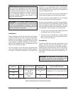
NOTE: For extractor sizing, typical CO
2
levels are
8.5% for natural gas and 9.5% for propane gas and
flue temperatures of approximately 150°F.
NOTE: Data for 100% firing rate.
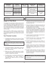
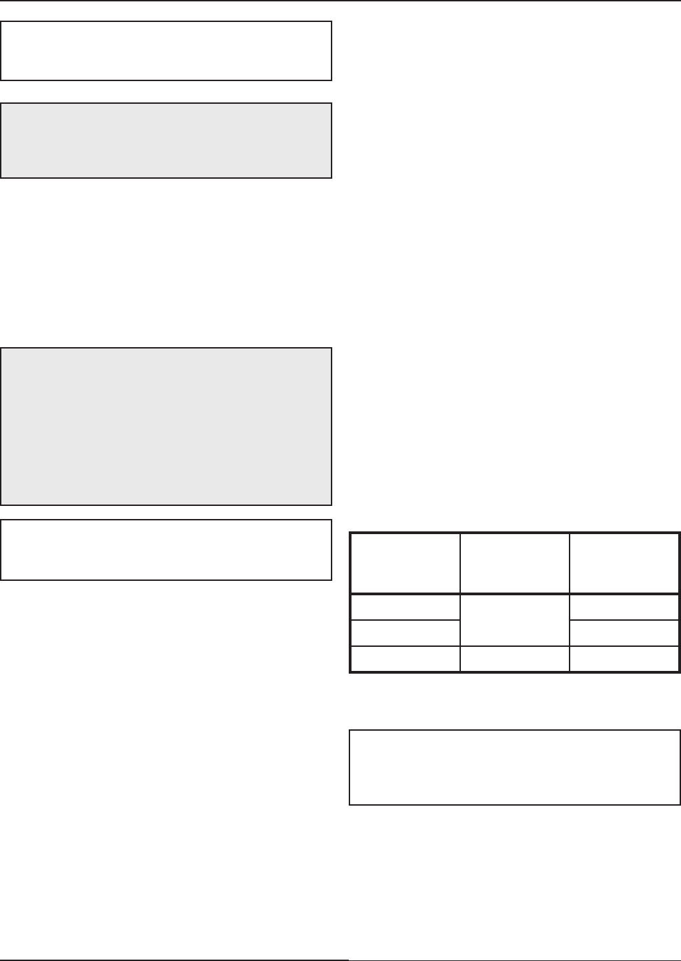
Table M: Volume of Flue Products Data
CAUTION: A listed vent cap terminal suitable for
c
onnection to the Cat IV vent materials, adequately
sized, must be used to evacuate the flue products
from the boilers.
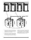
Common Venting
The NFGC does not address sizing guidelines for the
common venting of multiple Category IV heaters. This
is covered in the NFGC under “Engineered Vent Sys-
tems”. Table M provides volumes of flue products at
full fire for the calculation of appropriate vent and
extractor sizing for common venting.
Model No.
Vent Size
(inches)
Volume of
Flue Products
(CFM)
300
4
80
500 130
850 6 220
At the time of removal of an existing boiler, the follow-
ing steps shall be followed with each appliance
remaining connected to the common venting system
placed in operation, while the other appliances remain-
ing connected to the common venting system are not
in operation:
(a) Seal any unused openings in the common venting
system.
(b) Visually inspect the venting system for proper size
and horizontal pitch and make sure there is no
blockage or restriction, leakage, corrosion and
other deficiencies which could cause an unsafe
condition.
(c) As much as possible, close all building doors and
windows and all doors between the space in which
the appliances remaining connected to the com-
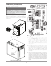
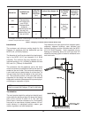
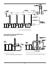
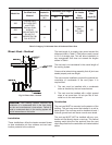
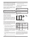
NOTE: Vent and intake piping must be supported so
that the weight of the venting is not transfered to the
unit. Horizontal runs of vent and intake piping must
be supported to prevent sagging.
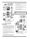
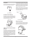
NOTE: When using PVC vent termination, insert the
round stainless mesh screens provided with the unit
into the tee and terminals.