


17
Electrical Power Connections
Installations must follow these codes:
• National Electrical Code and any other national,
state, provincial or local codes or regulations hav-
ing jurisdiction.
• Safety wiring must be NEC Class 1.
• Heater must be electrically grounded as required
by the NEC.
• In Canada, CSA C22. 1 C.E.C. Part 1.
The XFyre 300–850 heaters are wired for 120 V sin-
gle-phase 60 Hz power. Consult the wiring diagram
shipped with the heater. Before starting the heater,
check to ensure proper voltage to the heater and
pump(s). A larger circuit breaker may be needed for
pumps larger than 1/4 hp.
Boiler pumps up to 1 hp and DHW pumps up to 1/4 hp
get their power supply directly from the heater power
supply (connections in rear wiring box). XFyre heaters
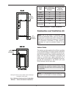
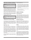
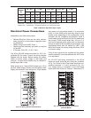
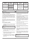
Natural Gas – 1,000 BTU/ft
3
, 0.60 specific gravity at 0.5 in. WC pressure drop
Propane Gas – 2,500 BTU/ft
3
, 1.53 specific gravity at 0.6 in. WC pressure drop
Table J: Maximum Equivalent Pipe Length
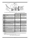
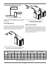
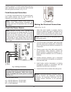
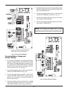
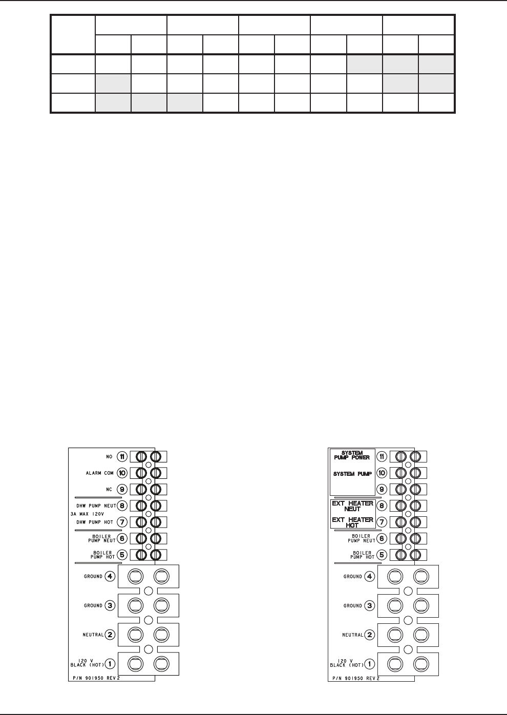
Fig. 11a: Wiring Electrical Connections
Model
N
o.
3/4” NPT 1” NPT 1-1/4” NPT 1-1/2” NPT 2” NPT
N P N P N P N P N P
3
00
1
5
3
0
4
5
1
00
1
75
4
00
3
90
500 10 15 40 65 150 150 350
850 15 25 55 55 125 175 450
may power up to two pumps directly (1 hp max boiler
pump, 3 A max DHW pump) and may control a third
system pump, depending on the configuration of the
controller and the installation requirements. Install a
circuit breaker sized sufficiently for both the heater and
the pump(s). DHW pumps larger than 1/4 hp or 3 A
must use a separate power supply and run the power
through an external field supplied pump contactor. Use
appropriately-sized wire as defined by NEC, CSA
and/or local codes. All primary wiring should be 125%
of minimum rating.
If any of the original wire as supplied with the heater
must be replaced, it must be replaced with 105°C wire
or its equivalent.
All 120 VAC field wiring connections to the XFyre
heater are made inside the rear wiring box as shown
in Fig. 11a. Power to the XFyre heater should be con-
nected to terminals 1, 2, and 3 as shown in Fig. 11a.
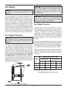
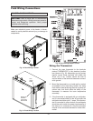
Low voltage wiring is connected to the field wiring
board at the front of the unit. Sensors, Thermostat (TT)
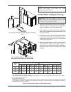
Fig. 11b: Wiring Electrical Connections
Cascade Master