


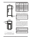
Relief Valve Installation and Piping
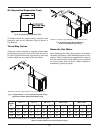
The heater is supplied with a Section IV “HV” stamped
relief valve sized for the full input of the unit. The relief
valve assembly is shipped loose and must be mount-
ed directly to the heater outlet. No valve shall be
installed between the heater and the relief valve. The
relief valve shall be mounted with its spindle vertical
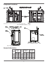
(see Fig. 1, 2 and 3 on page 6). Relief valve discharge
piping shall provide no less than the cross sectional
area of the relief valve outlet and must be routed to a
safe point of discharge. Installation must comply with
all national, state and local codes.
Temperature & Pressure Gauge
The temperature and pressure gauge is shipped loose
for field installation and must be installed within 12
inches of the boiler outlet (if possible) in an easily
readable location. Installation must comply with ASME
Section IV as well as all applicable national, state and
local codes.
Hydrostatic Test
Unlike many types of heaters, this heater does not re-
quire hydrostatic testing prior to being placed in
operation. The heat exchanger has already been fac-
tory-tested and is rated for 160 psi operating pressure.
However, Raypak does recommend hydrostatic test-
ing of the piping connections to the heater and the rest
of the system prior to operation. This is particularly
true for hydronic systems using expensive glycol-
based anti-freeze. Raypak recommends conducting
the hydrostatic test before connecting gas piping or
electrical supply.
Leaks must be repaired at once to prevent damage to
the heater. NEVER use petroleum-based stop-leak
compounds.
13
To perform hydrostatic test:
1. Connect fill water supply. With bleed valve open,
fill heater with water. When water flows from bleed
valve, shut off water. Close bleed valve. Carefully
fill the rest of the system, making sure to eliminate
a
ny entrapped air by using high-point vents. Close
feed valve. Test at standard operating pressure for
at least 24 hours.
2. Make sure constant gauge pressure has been
maintained throughout test.
3. Check for leaks. Repair if found.
Hydronic Heating
Pump Selection
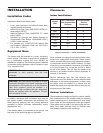
In order to ensure proper performance of your heater
system, you must install a correctly-sized pump. Ray-
pak recommends designing for a ∆T within the range
of 20°F to 40°F (5°C to 20°C). See Table G for accept-
able flow rates for each model (∆T is the temperature
difference between the inlet and outlet water when the
heater is firing at full rate).
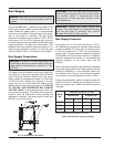
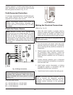
Feedwater Regulator
Raypak recommends that a feedwater regulator be in-
stalled and set at 12 psi minimum pressure at the
highest point of the system. Install a check valve or
back flow device upstream of the regulator, with a
manual shut-off valve as required by local codes.
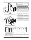
Piping
All high points should be vented. A heater installed
above radiation level must be provided with a low wa-
ter cut-off device (sales order option F-10). This
heater, when used in connection with a refrigeration
system, must be installed so that the chilled medium is
piped in parallel with the heater with appropriate
valves to prevent the chilled medium from entering the
heater.
The piping system of a hot water heater connected to
heating coils located in air handling units where they
may be exposed to circulating refrigerated air, must be
equipped with flow control valves or other automatic
means to prevent gravity circulation of the heater
water during the cooling cycle. It is highly recommend-
ed that the piping be insulated.
WARNING: Pressure relief valve discharge piping
must be piped near the floor and close to a drain to
eliminate the potential of severe burns. Do not pipe
to any area where freezing could occur. Refer to
l
ocal codes.
WARNING: The pressure relief valve must be
installed at the outlet of the boiler. No valve is
permitted to be installed between the boiler and the
relief valve.