


24
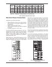
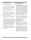
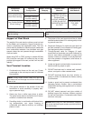
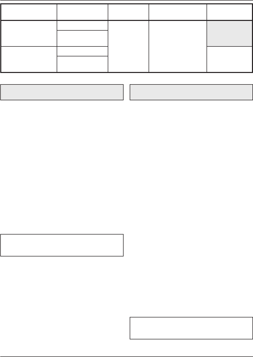
Table K: Venting Category Requirements
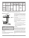
Vent Terminal Location
1. Condensate can freeze on the vent cap. Frozen
condensate on the vent cap can result in a blocked
flue condition.
2. Give special attention to the location of the vent
termination to avoid possibility of property dam-
age or personal injury.
3. Gases may form a white vapor plume in winter.
The plume could obstruct a window view if the ter-
mination is installed near windows.
4. Prevailing winds, in combination with below-freez-
ing temperatures, can cause freezing of
condensate and water/ice build-up on buildings,
plants or roofs.
5. The bottom of the vent terminal and the air intake
shall be located at least 12 in. above grade, includ-
ing normal snow line.
6. Single-wall Category IV metal vent pipe shall not
be used outdoors in cold climates for venting gas-
fired equipment without insulation.
7. Through-the-wall vents for Category IV appli-
ances shall not terminate over public walkways or
over an area where condensate or vapor could
create a nuisance or hazard or could be detrimen-
tal to the operation of regulators, relief valves, or
other equipment.
8. Locate and guard vent termination to prevent acci-
dental contact by people or pets.
9. DO NOT terminate vent in window well, stairwell,
alcove, courtyard or other recessed area.
10. DO NOT terminate above any door, window, or
gravity air intake. Condensate can freeze, causing
ice formations.
11. Locate or guard vent to prevent condensate from
damaging exterior finishes. Use a rust-resistant
sheet metal backing plate against brick or mason-
ry surfaces.
12. DO NOT extend exposed vent pipe outside of
building beyond the minimum distance required
for the vent termination. Condensate could freeze
and block vent pipe.
NOTE: During winter months check the vent cap
and make sure no blockage occurs from build-up of
snow or ice.
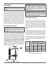
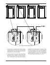
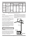
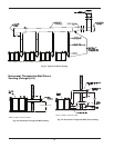
Support of Vent Stack
The weight of the vent stack or chimney must not rest
on the heater vent connection. Support must be pro-
vided in compliance with applicable codes. The vent
should also be installed to maintain proper clearances
from combustible materials. Use insulated vent pipe
spacers where the vent passes through combustible
roofs and walls.
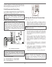
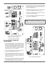
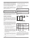
When using PVC or CPVC venting on models 300 and
500, insert the vent pipe 3-5 inches into the unit and
provide rigid support to the vent, so that it will not shift
laterally.
WARNING: Do not use foam core or cellular core
pipe for venting.
Combustion
Air Supply
Exhaust
Configuration
Heater Venting
Category
Certified Vent
Materials
Combustion Air
Inlet Material
From Inside Building
(Non-Direct Venting)
Vertical Venting
IV
(Canada Only: ULC-
S
636 PVC and CPVC)
Stainless Steel,
AL29-4C, ANSI/ASTM
D1785 Sch 40 PVC,
ANSI/ASTM F441 Sch
40 CPVC
H
orizontal Through-
the-Wall Venting
From Outside Building
(Direct Venting)
Vertical Venting
Galvanized Steel,
PVC, ABS,
CPVC
Horizontal Through-
the-Wall Venting
WARNING: DO NOT insulate PVC or CPVC vent
pipe.
NOTE: When using PVC vent termination, insert the
two round stainless mesh screens provided with the
unit into the tee.