


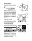
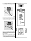
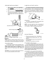
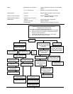
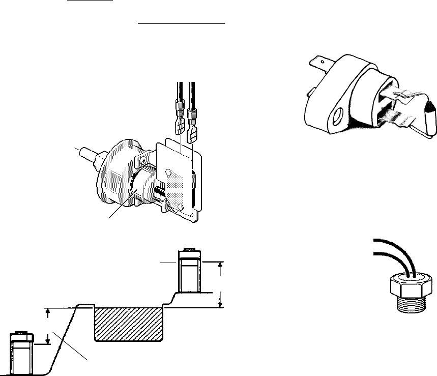
PRESSURE SWITCH ADJUSTMENT:
1. With pump and heater on, turn adjustment
knob (
clockwise) until a click is heard from the
gas valve.
2. Turn adjustment knob (counter clockwise) 1/4
turn.
3. Turn pump off and on several times. Heater
should shut off immediately. If it does not,
repeat steps above until proper adjustment is
made.
Adjustment Knob
Fig. # 8069.1
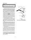
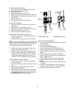
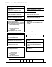
Heat Exchanger Height
Heat Exchanger Height
Pool or Spa
Fig. # 8152.0s
NOTE: If heater is installed outside of the limits shown,
a flow switch must be used in place of the pressure
switch when mounted and wired adjacent to the heater.
TWO SPEED PUMPS
In some cases, the flow on the low-speed is insuf-
ficient to operate the heater. This is apparent when the
pressure switch cannot be further adjusted or if the
heater makes banging noises. In these cases, the
pump must be run at high speed when heating the
water.
CAUTION: Do not operate the heater without the func-
tion of a properly adjusted pressure switch.
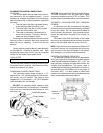
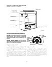
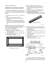
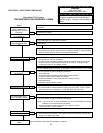
FLAME ROLL-OUT SAFETY SWITCH
The heater is equipped with a thermal cutoff device
to prevent flame roll-out in the event the heat exchanger
becomes blocked. This is a "Single-use" type fusible
link or thermal fuse, that must be replaced when dis-
abled by an over temperature condition, caused by
excessive restriction in the heat exchanger flue pas-
sage.
Fig. #9177
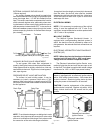
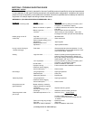
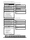
HIGH LIMITS
The heater is equipped with two automatic high
limits. Set to operate at 135°F and 140°F.
NOTE: An erratic high limit is often characteristic of
internal heat exchanger problem, i.e. scale buildup,
U.G. operation. Refer to troubleshooting section.
Fig. # 8159.0s
HIGH LIMIT REMOVAL
1. Disconnect top portion of unit. (See heat ex-
change removal procedure step 1 thru 7 and
step 10)
2. Remove defective high limit and replace with
new high limit.
3. Reverse above procedure to reinstall.
PILOT SAFETY (Millivolt System)
The heaters equipped with the standing pilot (milli-
volt system), have pilot generators which act as a safety
device to shut off the flow of gas to the main burners and
the pilot burner in case the pilot flame is extinguished.
The pilot burner must be manually relighted to place the
heater in operation again. Refer to the lighting instruc-
tions provided on the heater label.
PILOT SAFETY (IID Units) ELECTRIC IGNITION
The heater employs a pilot safety which closes the
main gas valve within 8/10ths of a second whenever the
pilot flame is interrupted. Pilot flame is automatically lit
when the device is powered. Unit performs its own
safety check and opens the main valve only after the
pilot is proven to be lit.
18
5' Max.
5' Max.