SECTION 4 / SERVICING INSTRUCTIONS
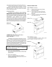
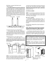
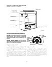
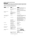
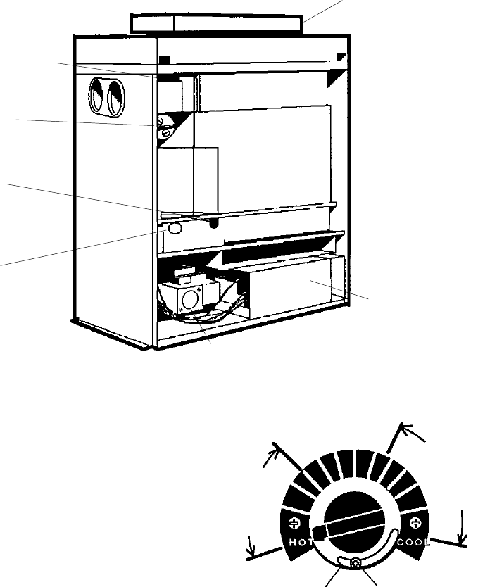
GENERAL LOCATION OF CONTROLS
Drain Valve
Solid State Thermostat &
Ignition Control
Pressure Switch
Burner & Pilot
Thermal Fuse
CONTROLS/ADJUSTMENTS/REPLACEMENTS
CAUTION: Label all wires prior to disconnection when
servicing controls. Wiring errors can cause improper
and dangerous operation. Verify proper operation after
servicing.
DANGER - SHOCK HAZARD -make sure electrical
power to the heater is disconnected to avoid potential
serious injury of damage to components.
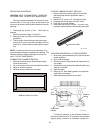
TEMPERATURE CONTROLS
The water temperature is controlled by the heater
thermostat on the upper front panel of the heater. The
control center contains an On/Off toggle switch and a
thermostat. The switch functions as a means for turning
the heater on or off.
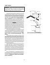
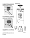
The thermostat is fitted with a means of limiting the
upper temperature limit below the maximum level. The
knob stop adjustment ring illustrated below is adjust-
able by loosening the set screw, rotating the knobstop
ring to the desired location and retightening the set
screw.
Knobstop Ring Set Screw
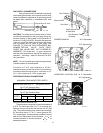
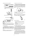
PRESSURE SWITCH
The pressure switch, or heater actuator, insures
that the heater operates only when the filter pump is in
operation. It is factory set at 1.75 PSI for deck level
installations. When the heater is located below the level
of the spa or pool, it may be necessary to reset the
pressure switch to compensate for the no-flow static
head. If it is necessary to reset the pressure switch, we
recommend that following procedure:
17
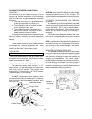
HIGH LIMITS
(Located in the
Inlet/Outlet header)
Fig. # 8160.1s
Gas Valve
Typical
Comfortable
Pool
Temperature
Range
Typical
Comfortable
Spa
Temperature
Range


