


throughout its entire length and must pitch downward
from the valve. No shut-off valve shall be installed
between the relief valve and the drain line. Valve lever
should be tripped at least once a year to ensure that
waterways are clear.
ELECTRICAL WIRING
NOTE: If it is necessary to replace any of the original
wiring, it must be replaced with 105 °C wire or its
equivalent, except all black wire must be replaced with
150 °C wire or its equivalent.
MILLIVOLT SYSTEM
The Millivolt System Residential Heater is
equipped with a self-generating electrical system in
which the electric current is provided by means of a
pilot generator. No external electrical connections are
required.
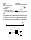
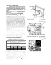
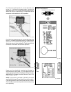
ELECTRONIC INTERMITTENT IGNITION DEVICE
SYSTEM (IID)
NOTE: When the electrical hookup to the heater
requires both 24V and 115V or 240V, each input
voltage must be isolated in separate conduit.
The Electronic Intermittent Ignition Device auto-
matically lights the pilot and main burners upon a call
for the heat. The heater is supplied with a dual voltage
transformer for 120V or 240V input power hookup.
NOTE: IID Propane Units Only
Heater is equipped with an electronic ignition device
with a 100% safety lockout feature. If the heater fails
to start or lockout. Reset the ignition device by inter-
rupting the power to the heater for 60 seconds.
CAUTION: If service replacement of the electronic
ignition device is required. Replace only with a 100%
safety lockout device with 90 second trial for pilot
ignition.
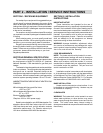
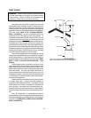
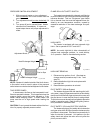
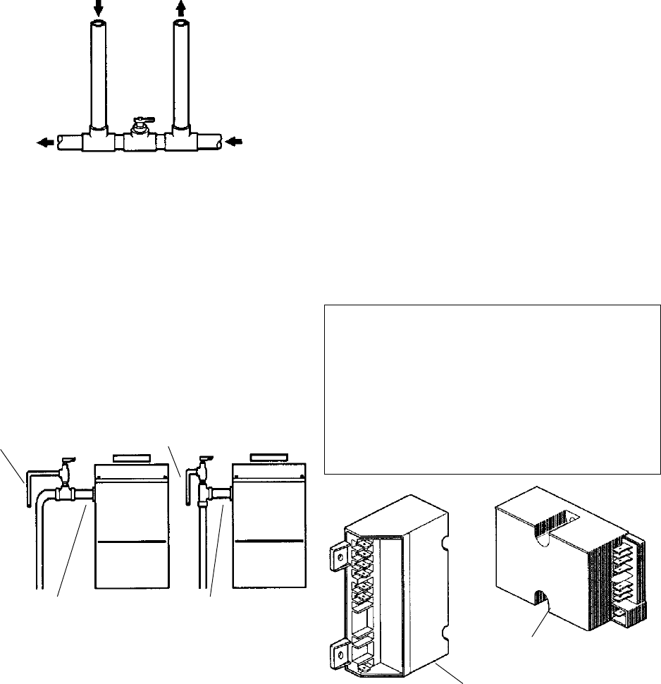
EXTERNAL AUXILIARY BYPASS VALVE
(Where required)
An auxiliary bypass valve should be used when
flow rates exceed 60 GPM (usually a high performance
pump size larger than 1 1/2 HP will exceed this flow
rate). This valve is required to complement the function
of the automatic bypass valve, particularly when start-
ing the heater in winter or early spring when the spa or
pool temperature is down below 55°F. It also serves to
eliminate needless pressure drop through the heater
and accompanying reduction in the flow rate to the spa
jets, etcetera.
From Heater To Heater
To Pool From Pool
Auxiliary Bypass Valve (do not use gate valve)
AUXILIARY BYPASS VALVE ADJUSTMENT
To set bypass: With clean filter, adjustment is
made by feeling the inlet and outlet pipes at the heater.
Outlet pipes should be slightly warmer than inlet and
comfortable to the touch. If pipe is hot, close bypass; if
cold, open bypass
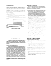
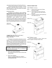
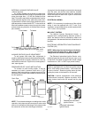
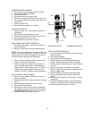
PRESSURE RELIEF VALVE INSTALLATION
To conform to local building codes, it may be
necessary to install a pressure relief valve. A 3/4"
pressure relief valve having a capacity equal to BTU/
HR output of the model to be installed is recommended
for this appliance.
Fig. # 8150.0s
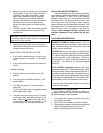
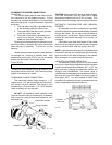
NOTE: To avoid water damage or scalding due to valve
operation, drain pipe must be connected to valve outlet
and run to a safe place of discharge. Drain pipe must be
the same size as the valve discharge connection
Drain Pipe Drain Pipe
Heater Outlet Heater Outlet
Fig. # 8157.0s
13
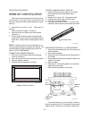
Fig. # 8929.1
Robertshaw Intermittent
Ignition Device
Honeywell Intermittent
Ignition Device
Fig. # 8085