


SPK
14
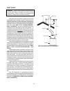
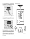
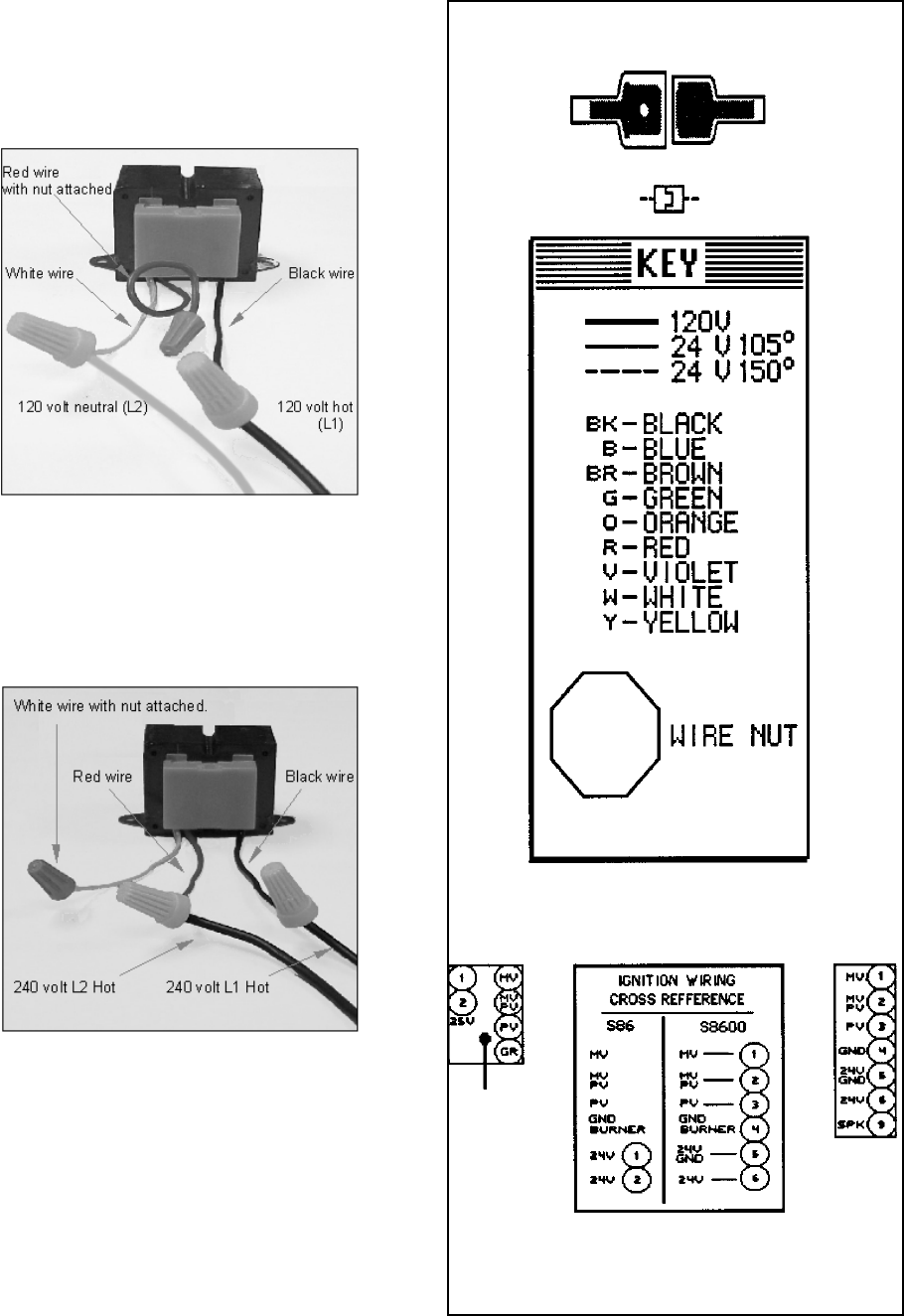
WIRING DIAGRAM KEY
Fig. # 8096
Fig. # S86/S8600
S86 S8600
PINK CONNECTOR BLUE CONNECTOR
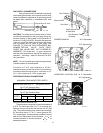
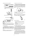
For 120 V input power to the unit, connect the black wire
to the “L1” or hot leg of the power supply. Connect the
white wire to the “L2” or neutral leg of the power supply.
Attach the wire nut to the red wire. There should be no
connection to the red wire for 120V operation.
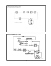
Fig. #9240
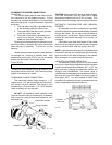
For 240 V input power to the unit, connect the black wire
to the “L1” or hot leg of the power supply. Connect the red
wire to the “L2” or second hot leg of the power supply.
Attach the wire nut to the white wire. There should be no
connection to the white wire for 240V operation.
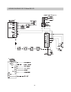
Fig. # 9241
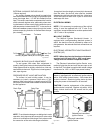
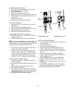
Heater must be electrically grounded and bonded in
accordance with local codes, or, in the absence of local
codes, with the latest edition of the National Electrical code,
ANSI/NFPA 70 (Canada-Canadian Electrical Code, CSA
C221.1, Part 1 and 2).
NOTE: Input power to the heater (120/240V) should be
supplied from the load (Pump) side of time clock or switch.
Connecting heater to continuous power source will allow
"Fail" indications (service and pressure switch) when pump
is not operating.