


15
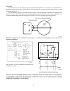
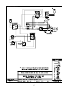
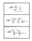
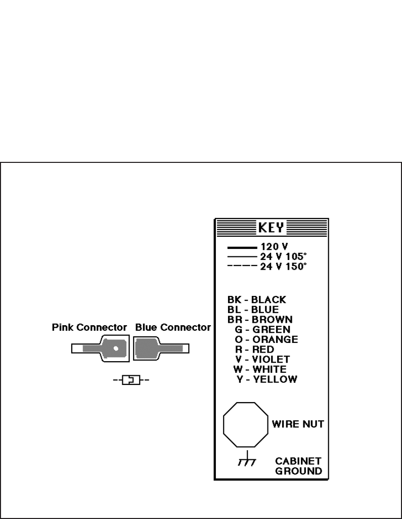
WIRING DIAGRAM KEY
Fig.# 8096.2
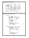
The room thermostat should be installed in accordance
with the manufacturer's instructions. The thermostat heat
anticipator should be set at 1.0 ampere (automatic
ignition) and 0.60 ampere (standing pilot) for single- zone
installations. For multi-zone applications, the heat antici-
pator setting should be based on the ampere load in the
thermostat circuit.
NOTE: If it is necessary to replace any of the original
wiring, it must be replaced with 105°C wire or its
equivalent, except 150° C black wire must be replaced
with 150°C wire or its equivalent. See Wiring Diagram Key
for 150°C wire indication.
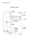
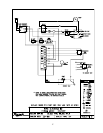
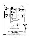
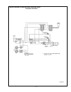
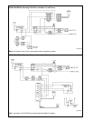
ELECTRICAL WIRING
The electrical power supply requirement for these
boilers is 115 volts, 60 Hz. Field wiring connections and
electrical grounding must comply with the local codes,
or in the absence of local codes, with the National
Electrical Code, ANSI/NFPA 70-1987. Provide a sepa-
rate fused circuit from the main electrical panel to the
boiler, and a disconnecting means within sight of the
boiler.
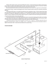
Remove the control box cover and make the power
supply connections in the field wiring compartment.
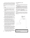
(See general location of controls drawing on page 23).
The pump is supplied and factory-wired to operate with
the boiler. The "TH" wire leads are for the room thermo-
stat or zone valve connections.