


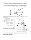
The gas valve is provided with pressure taps to
measure gas pressure upstream of the gas valve and
downstream which is the same as the manifold pres-
sure.
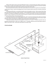
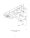
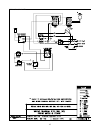
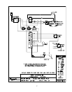
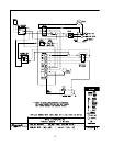
WATER CONNECTIONS & SYSTEM PIPING
The pipe size for water connections is shown on
page 3. Typical piping systems are shown on pages 12
to 14.
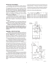
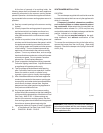
The boiler is supplied with a circulator and built in
bypass as standard to ensure the required minimum
water flow in the boiler. The bypass on models H-0135
and H-0180 is provided with an adjustable valve that is
factory-set in the full open position. The handle is shipped
loose. The full open position is appropriate for most
systems, and ensures adequate flow through the boiler.
If system flow is inadequate, (indicated by excessive
temperature drop through the system) the bypass valve
can be throttled slightly. Care must be taken against over
-throttling which may lead to inadequate flow through the
boiler and boiler harmonics (a humming sound from the
heat exchanger). If adequate system flow cannot be
obtained without causing harmonics, an additional pump
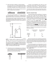
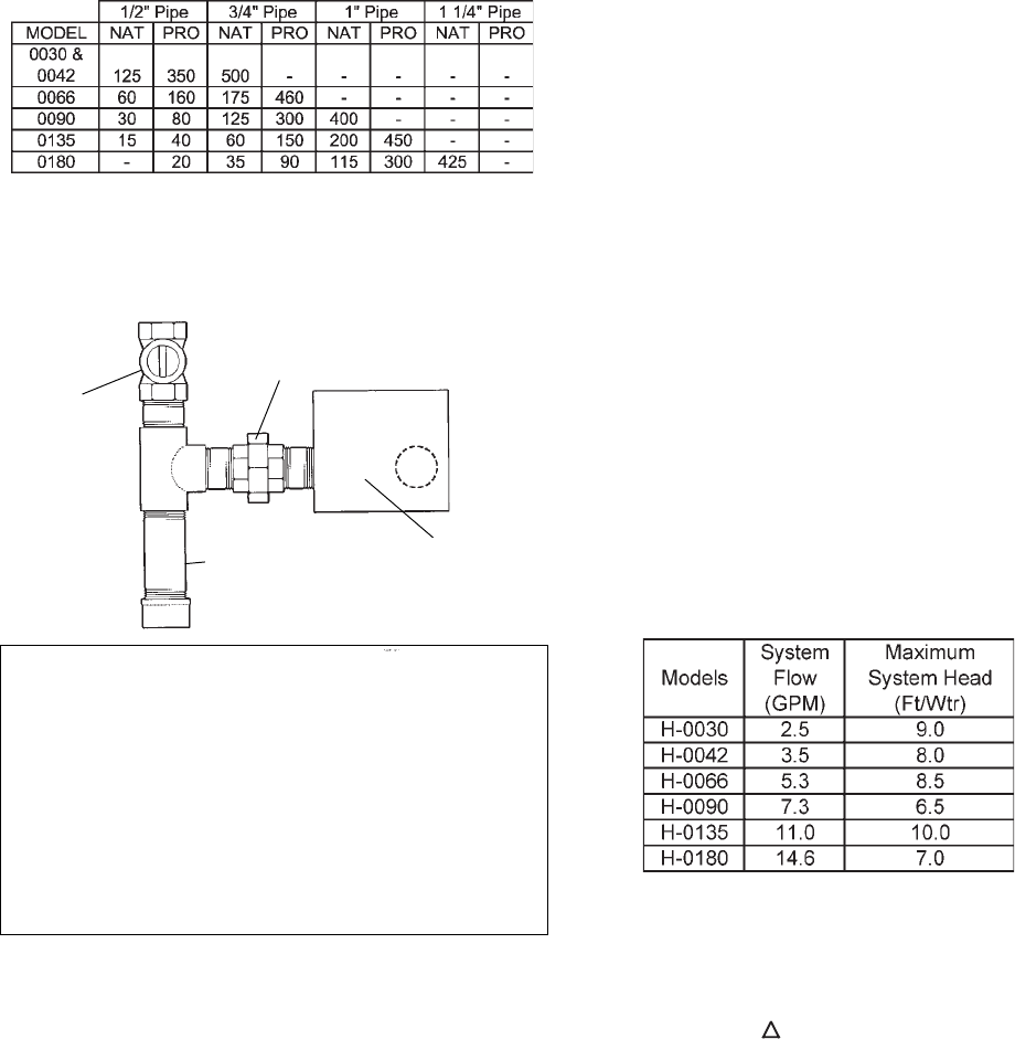
is required. The factory-mounted circulator will provide
adequate water flow for systems designed at a 20°F
temperature drop, and system pressure drop or head not
exceeding that which is shown below.
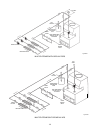
When the total system head exceeds the available
head pressures, a primary/secondary pumping system
is recommended.
The minimum boiler operating temperature
should be 105°F. When operating at low tempera-
ture applications, T (temperature rise) must be
20°F or less.
Propylene glycol solution is commonly used in the
heating system when freeze protection is required. This
will affect the system design and pump performance. As
a rule of thumb, 50% solution of propylene glycol will
require the system flow (GPM) to increase by 14%, and
the system head (Ft/Wtr) by 23% in order to maintain the
same heat transfer load.
11
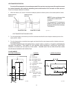
GAS SUPPLY CONNECTIONS
The inlet gas connection of the boiler gas valve is
1/2". Provide an adequate gas piping supply line no
smaller than 1/2", according to the chart below:
Maximum Equivalent Pipe Length (Feet)
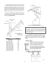
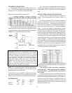
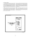
Gas piping must have a sediment trap ahead of the
boiler gas controls, and a manual shut-off valve located
outside the jacket. All gas piping should be tested after
installation in accordance with local codes.
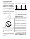
CAUTION: The boiler and its manual shut-off valve must be
disconnected from the gas supply during any pressure
testing of that system at test pressures in excess of 1/2 psig
(3.45 KPA). Dissipate test pressure in the gas supply line
before reconnecting the boiler and its manual shut-off valve
to gas supply line. FAILURE TO FOLLOW THIS PROCE-
DURE MAY DAMAGE THE GAS VALVE. OVER PRES-
SURED GAS VALVES ARE NOT COVERED BY WAR-
RANTY. The boiler and its gas connections shall be leak
tested before placing the appliance in operation. Use soapy
water for leak test. DO NOT use open flame.
NOTE: Do not use teflon tape on gas line pipe thread.
A flexible sealant suitable for use with Natural and
Propane gases is recommended.
These boilers are also certified to operate on propane
gas, when equipped with the combination gas valve and
orifices (pilot and main burners) sized for propane gas.
GAS PRESSURE
Inches W.C. Regulator
Min. Max. Setting
Natural 7.0 14.0 3.5
Propane 12.0 14.0 11.0
Sediment Trap Gas Valve
Manual Union
Valve
Fig. # 8192.0