


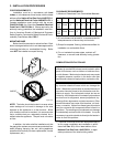
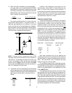
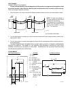
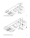
2) When the boiler is installed in a confined space
such as a utility room or closet (Models 0030,0042
and 0066 only), where all air is supplied from inside
the building, the boiler room must be provided with
two openings, each one having a minimum net free
area, in square inches as follows:
Model Sq. In. of Free Area
0030, 0042 & 0066 100
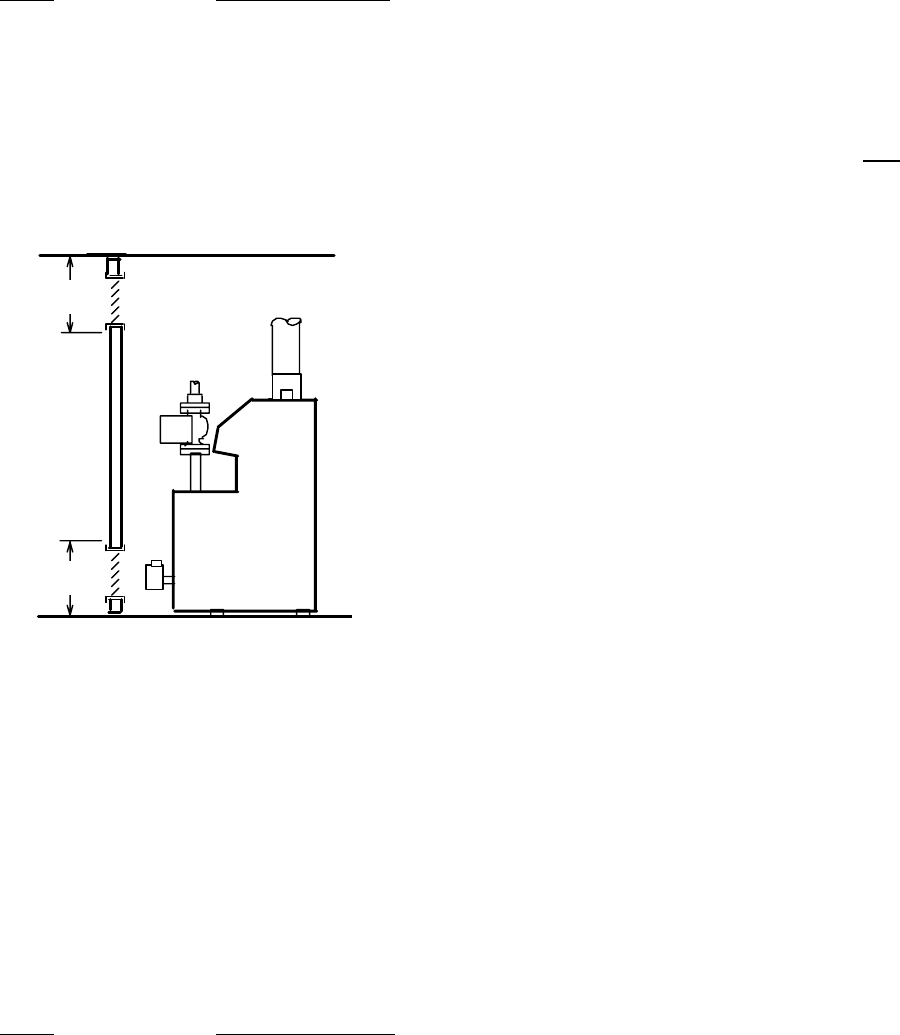
One opening shall be within 12 inches of the top,
and the other opening within 12 inches of the floor. If
additional gas appliances are installed in the same
space, the total input of all gas appliances installed in
the same space, must be considered in the calculation.
Refer to Sec. 5.3.5 of the latest edition of the National
Fuel Gas Code for additional requirements.
Fig. #8198.0
NOTE: If louvers, grills or screens are used on the
openings, obtain the net free area from their supplier or
manufacturer. If the design free area of a louver is not
known nor available, it shall be assumed that wood
louvers will have 20-25 percent free area and metal
louvers will have 60-75 percent free area as shown in
Sec. 5.3.5 National Fuel Gas Code.
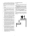
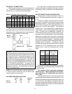
3) If the boiler room is located against an outside wall
and air openings can communicate directly with the
outdoors, the two openings on the outside wall must
each have a net free area, in square inches as
follows:
Model Sq. In. Of Free Area
0030 & 0042 12
0066 18
0090 24
0135 35
0180 45
Location of the openings is the same as in the
previous case - that is, within 12 inches of the top, and
within 12 inches of the bottom of the enclosure. If
horizontal ducts are used, the area must be doubled and
the duct area shall not be less than the area of the
openings they connect, and in no case shall the small-
est dimension be less than 3 inches.
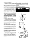
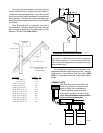
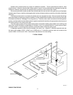
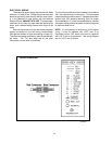
VENTING CONNECTIONS
These boilers have built-in drafthoods. Vent piping
the same size or larger than the draft hood outlet is
recommended; however, when the total vent height
(drafthood outlet to vent terminal) is at least ten (10)
feet, the vent pipe size may be reduced by one size only
as specified in Part 11, Note 2 and in Appendix G of the
latest edition of the National Fuel Gas Code, ANSI Z
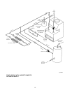
223.1. As much as possible avoid horizontal runs of
vent pipe and too many elbows. If installation requires
horizontal runs, the vent pipe must have a minimum of
1/4 inch per foot rise and should be supported at not less
than five foot intervals. Maximum vent connector hori-
zontal length shall be 1-1/2 feet (18 inches) for each inch
of connector diameter as follows.
Boiler Size Vent Connector Max Horizontal
Diameter Length - FT
30 & 42 4" 6
66 & 90 5" 7.5
135 6" 9
180 7" 10.5
Gas Vents supported only by the flashing and
extending above the roof more than five feet should be
securely guyed or braced to withstand snow and wind
loads. We recommend use of insulated vent pipe
spacer through the roofs and walls.
For protections against rain or blockage by snow,
the vent pipe must terminate with a listed vent cap which
complies with the local codes or, in the absence of such
codes, to the latest edition of the National Fuel Gas
Code, ANSI Z 223.1.
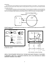
The discharge opening must be a minimum of two
feet vertically from the roof surface and at least two (2)
feet higher than any part of the building within ten (10)
feet. Vent stack shall be at least five (5) feet in vertical
height above the drafthood outlet. The vent cap location
shall have a minimum clearance of four (4) feet horizon-
tally from, and in no case above or below, unless a 4-foot
horizontal distance is maintained, from electric meters,
gas meters regulators and relief equipment.
12"
12"
5