


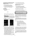
LOW WATER CUT OFF WHEN INSTALLED
The low water cut off automatically shuts down
burner whenever water level drops below probe. 90
second time delay prevents premature lockout due to
temporary conditions such as power failure or air pock-
ets. Flush float type devices at beginning of each
heating season.
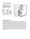
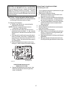
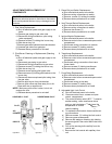
PROCEDURE FOR CLEANING FLUE GAS
PASSAGE-WAYS
Soot will clog areas behind fins and cause eventual
tube failure. Any sign of soot at base of burners or
around outer jacket indicates a need for cleaning.
1. Lift off draft hood and flue collector by removing
bolts and screws.
2. Remove "V" baffles from heat exchanger.
3. Remove burner tray, see Burner Drawer Removal.
4. Take garden hose and wash heat exchanger, mak-
ing sure soot is removed from between fins.
(Avoid excessive water against refractory).
5. Reassemble; when boiler is fired, some steam will
form from wet refractory. This is normal.
NOTE: In extreme cases it may be necessary to
remove the heat exchanger completely for cleaning.
The simplest method is steam cleaning at a local car
wash. DO NOT WIRE BRUSH!
CAUTION:
Soot is combustible, so exercise extreme care.
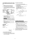
BURNER DRAWER REMOVAL
1. Shut off power and gas supply to the boiler. Dis-
connect union(s) and pilot tubing when present;
then loosen and remove burner hold down screws.
2. Disconnect wires at gas valve and slide burner
drawer out.
MAIN BURNER AND ORIFICE REMOVAL
1. Remove screws and burner hold down bracket.
NOTE: If the heat exchanger is sooted badly, the
burner hold down bracket and spacer can become
distorted from direct flame impingement and this usu-
ally necessitates replacement of these parts.
2. Lift burners from slotted spacer and slide from
orifices. Clean with a wire brush.
3. Orifices usually do not need to be replaced. To
clean, run either copper wire or wood through
orifice. Do not enlarge hole. To remove orifice, use
a socket wrench and remove the manifold. DO
NOT overtighten when reinstalling.
29
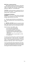
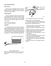
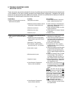
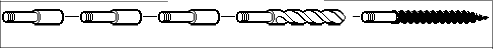
Extension Pieces (5) Auger with Carbide Tip Wire Brush
Fig. #8154
Another method is to remove the heat exchanger,
ream tubes and immerse heat exchanger in non-inhib-
ited de-scale solvent.
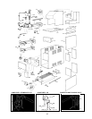
HEAT EXCHANGER REMOVAL
1. Shut water, gas and electricity off, close valves and
relieve pressure, remove relief valve. Remove side
inspection panels.
2. Remove top holding screws.
3. Remove draft diverter, lift and remove top and flue
collector on stack type models. Remove inspection
panels.
4. Loosen bolts and disconnect flange nuts on inlet-
outlet header, loosen union(s) at gas pipe, and slide
boiler away from piping until studs clear the heater.
5. Remove heat exchanger corner brackets.
REPAIR SECTION
TUBE CLEANING PROCEDURE (TYPICAL)
Establish a regular inspection schedule, the fre-
quency depending on the local water condition and
severity of service. Do not let the tubes clog up solidly.
Clean out deposits over 1/16" in thickness.
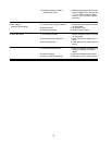
The boiler may be cleaned from the side opposite
the water connections as shown, without breaking pipe
connections. It is preferable, however, to remove both
headers for better visibility through the tubes and to be
sure the residue does not get into the system.
Note that you do not remove the top pan or the heat
exchanger generally.
After reaming with the auger, mount the wire brush
and clean out the debris remaining in the tubes.
RAYPAK TUBE CLEANING KIT