


10
Quadra-Fire • Sapphire • 7055-116 Rev. D • 6/11
5
Vent Information
A. Venting Components
B. Use of Elbows
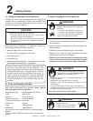
In order to comply with applicable codes and product
warranties, use only following venting components:
• Hearth & Home Technologies (HHT)
• Security Chimney's Secure Vent Chimney System
• Selkirk Metalbestos
• AmeriVent
• Simpson Dura-Vent (SDV)
DO NOT USE FIELD-FABRICATED VENTING
COMPONENTS. Refer to the venting manufacturer’s
instructions.
This product is approved to be vented either horizontally,
through the side wall or vertically through the roof. You may
vent through a Class A or masonry chimney if an approved
adapter is used.
This appliance is a direct vent heater. All combustion air must
come directly from the outside of the building. The vent pipe
for this unit consists of an inner and an outer pipe. The inner
pipe carries the appliance exhaust out of the system, and the
outer pipe brings fresh combustion air into the appliance.
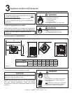
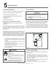
Fire Risk.
Explosion Risk.
Asphyxiation Risk.
Do NOT connect this gas appliance to a chimney
fl ue serving a separate solid-fuel or gas burning
appliance.
• Vent this appliance directly outside.
• Use separate vent system for this appliance.
May impair safe operation of this appliance or
other appliances connected to the fl ue.
WARNING
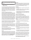
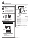
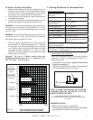
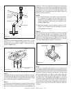
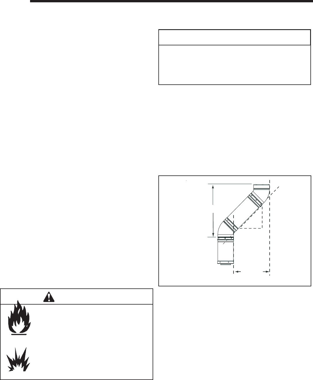
Diagonal runs have both vertical and horizontal vent aspects
when calculating the effects. Use the rise for the vertical
aspect and the run for the horizontal aspect. Figure 5.1.
Two 45° elbows may be used in place of one 90° elbow. On
45° runs, one foot of diagonal is equal to 8-1/2 in. (216mm)
horizontal run and 8-1/2 in. (216mm) vertical run. A length
of straight pipe is allowed between two elbows. Figure 5.1.
Vertical
Horizontal
12 in.
8-1/2 in.
8-1/2 in.
Vertical and horizontal measurements were made using the
following standards.
C. Measuring Standards
CAUTION
ALL vent confi guration specifi cations MUST be followed.
• This product is tested and listed to these
specifi cations.
• Appliance performance will suffer if specifi cations are
not followed.
Figure 5.1
• Pipe measurements are from center line to center line.
• Horizontal terminations are measured to the outside of
the mounting surface (fl ange of termination cap). See
Figure 4.1 on page 8.
• Vertical terminations are measured to the top of the last
pipe before termination cap.
• Horizontal pipe installed level with 1/4 in.(6mm) rise.
• A round support box/wall thimble or heat shield is
required when the venting passes through a combus-
tible wall.
• A support box or ceiling fi restop is required when the
venting passes through a ceiling.
• Roof fl ashing and a storm collar are required when
venting passes through the roof.
• Follow instructions provided with the venting for instal-
lation of these items.