Quadra-Fire • QVI-30FB-S • 2020-910 Rev. H • 6/09
10
CAUTION
ALL vent specifi cations MUST be followed.
• This product is tested and listed to these specifi cations.
• Appliance performance will suffer if specifi cations are not
followed.
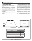
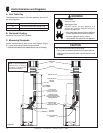
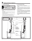
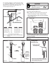
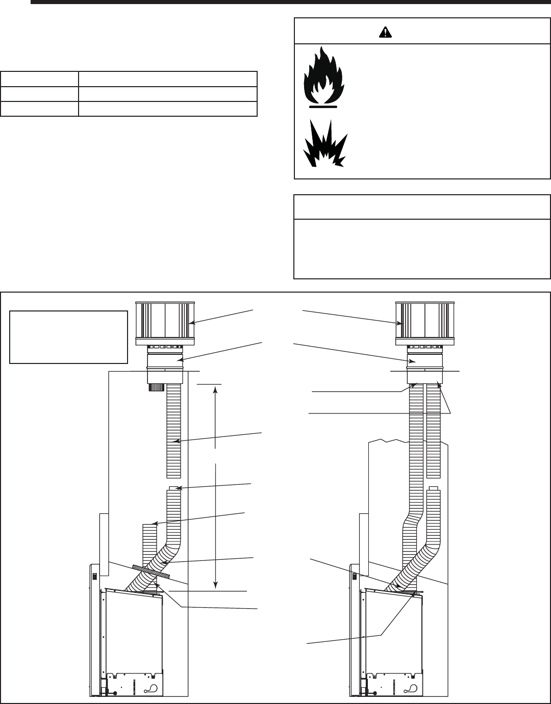
Figure 5.1
C. Measuring Standards
Vertical measurements listed in the vent diagram (Figure
5.1) were made using the following standard:
• Vertical terminations are measured to top of chimney.
Fire Hazard.
Explosion Risk.
Asphyxiation Risk.
Do NOT connect this gas appliance to a
chimney fl ue serving a separate solid fuel or
gas burning appliance.
• May impair safe operation of this appliance
or other appliances connected to the fl ue.
• Vent this appliance directly outside.
• Use separate vent system for this appliance.
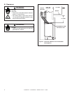
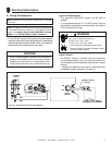
B. Horizontal Venting
Horizontal venting is NOT allowed.
5
5
Vent Information and Diagrams
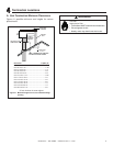
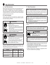
A. Vent Table Key
The abbreviations listed in this vent table key are used in
the vent diagrams.
Symbol Description
V
MIN
Minimum Vertical Run Length 14 ft.
V
MAX
Maximum Vertical Run Length 50 ft.
WARNING
TERMINATION
CAP
ADAPTOR
EXHAUST
VENT PIPE
V= 14 FT. MINIMUM
50 FT. MAXIMUM
3 INCH COLLAR
(Factory installed to
stainless steel section)
WARNING: DO NOT
BLOCK PIPE END WITH
INSULATION OR ANY OTHER
SEALING MATERIAL
STAINLESS STEEL
PIPE - 3 FT. MIN.
REQUIRED (INCLUDED)
INLET AIR
VENT PIPE
COLLAR ATTACHMENT
BRACKET
EXHAUST COLLAR
INLET AIR COLLAR
Note: To achieve optimum
performance of insert,
minimize or avoid bends
in exhaust vent pipe.


