


12.0 Changing Components
32
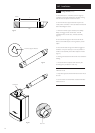
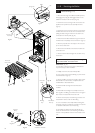
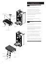
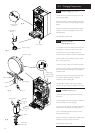
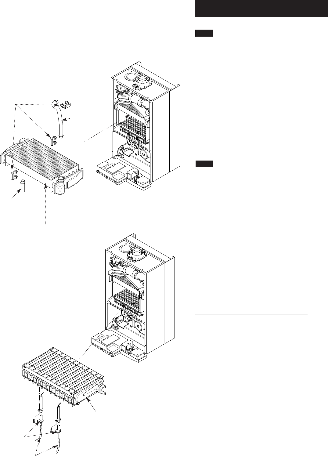
12.3 Heat Exchanger (Fig. 50)
1. Remove the fan as described in section 12.1.
2. Drain the primary circuit. Prise the three pipe
connecting clips off the joints in the flow and return
pipes. Remove the heat exchanger return pipe.
3. Lift the heat exchanger to disconnect the flow pipe
joint. Withdraw it from the appliance, taking care not to
damage the rear insulation piece.
4. Fit the new heat exchanger.
5. Reassemble in reverse order of dismantling, and
repressurise the system.
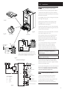
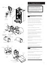
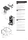
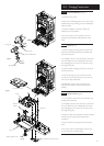
12.4 Burner (Fig. 51)
1. Remove the four screws securing the combustion box
door and remove the door.
2. Undo the screws securing the burner to the injector
manifold. Draw the burner out of the combustion box,
pulling the electrode grommets from the slots in the
combustion box lower panel.
3. Disconnect the electrode leads and grommets from
the electrodes. Completely remove the burner.
4. Undo the screws securing the electrodes to the
burner. Examine the condition of the electrodes,
replacing if necessary. Fit the electrodes to the new
burner.
5. Engage the burner location brackets over the studs on
the injector manifold and reassemble in reverse order.
Burner
Electrode
Grommets
Electrode
Leads
Electrodes
Fig. 50
Fig. 51
Heat Exchanger
Pipe Connecting
Clips
Flow Pipe
Heat Exchanger
Return Pipe