


8.0 Installation
25
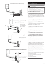
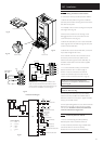
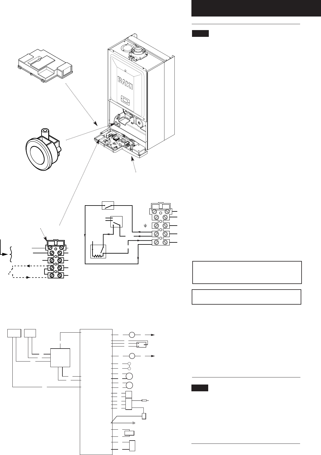
8.8 Making The Electrical Connections
To connect the mains input cable proceed as follows:-
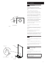
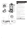
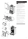
1. Slacken the facia panel securing screws and lift the
outercase panel so that its securing tabs are clear of the
facia. Remove the panel.
2. Completely undo the screws securing the facia panel
and hinge it down (Fig. 26).
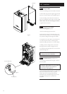
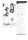
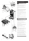
3. Remove the control box cover securing screws.
Disengage the barbs on the control box from the
cover. Remove the cover (Fig. 27).
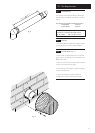
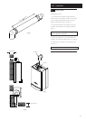
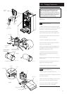
4. Slacken the cable clamp on the LH side of the boiler
chassis (Fig. 28). Insert the cable through the clamp and
route it to the terminal block.
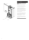
5. Slacken the screws in the terminal block, connect the
input cable, and tighten the screws.
6. If an external control is to be connected it can be
done at this point. Run the input cable from the
external control through the second cable clamp on
the boiler chassis. Refer to the instructions supplied
with the control.
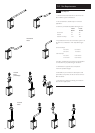
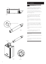
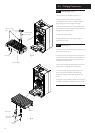
7. To connect external control(s) remove the link
between terminals 1 & 2. The 230V supply at
terminal 1 must be connected to the external
control. The switched output from the external
control must be connected to terminal 2. (Fig. 29).
NOTE: If the room thermostat being used
incorporates an anticipator it MUST be wired as
shown in Fig. 29
IMPORTANT: The external control MUST be
suitable for 230V switching.
8. Ensure that both mains input and, where fitted,
external control input cables have sufficient slack to
allow the control box to drop down. Tighten the cable
clamp(s) on the boiler chassis.
9. If the optional integral timer is to be used it should be
fitted at this point. Refer to the instructions supplied
with the timer.
NOTE: An external frost thermostat
cannot be used with the integral timer.
8.9 Preliminary Electrical Checks
1. Prior to commissioning the boiler preliminary
electrical system checks should be carried out.
2. These should be performed using a suitable meter,
and include checks for Ground Continuity,
Resistance to Ground, Short Circuit and Polarity.
Always fit fast
blow 2A fuse
Fused supply 3A
230V ~ 50Hz
Live (brown)
Neutral (blue)
Earth (green/yellow)
1
2
230V
br
b
g/y
bk
bk
b
br
bk
bk
g/y
1
N
L
Frost Thermostat
Room Thermostat
External Clock
2
N
230 V
N
L
SL
L
230 V
Selector /
Reset Switch
External
Controls
N
br b
Pump
Hydraulic Differential Pressure Switch
r
r
DHW Flow Priority Microswitch
g
g
Safety Overheat Thermostat
Flue Thermostat
b
b
Central Heating
NTC Sensor
r
r
Gas Valve
Spark Electrode
Condensate Trap
Flame Sensing Electrode
N
br b
Fan
bk
bk
b
br
bk
Pressure Switch
b
br
bk
PCB
b
b
br
r
bk
bk
br
DHW
NTC Sensor
g
g
Gas Valve Modulator
Fig. 28
Fig. 27
Fig. 29
Fig. 30
Fig. 26
Terminal Block
Fuse
Cable Clamp
Control Box Cover
Facia Panel
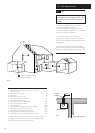
Functional Flow Diagram
Key to Wiring
b - blue
br - brown
bk - black
r - red
g - green
IMPORTANT: If an integral timer is fitted to the
boiler an external frost thermostat wired as shown
will not operate correctly. Only external timers may
be used in such installations, as in the diagram.