


9 L80-029 Rev 5 10/07
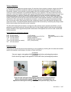
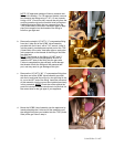
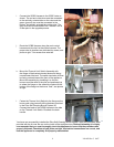
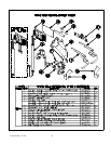
i. Connect the SCBS Harness to the SCBS Valve as
shown. The red and violet wires must be connected
to the vertically oriented tabs on the valve and the
green (ground) wire must be connected to the
bottom, horizontally oriented tab on the valve. The
grey wires will be connected to the Thermal Limit at
a later point in the upgrade process.
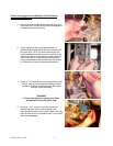
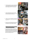
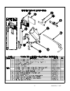
j. Route the SCBS Harness along the main control
harness and wire tie it to the control harness. The
proper wire tie locations are indicated by arrows, see
photo at right. Trim excess from wire ties.
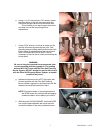
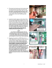
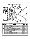
k. Mount the Thermal Limit Switch Assembly with
the flange of the bracket oriented down and facing
inward toward the tank. The switch terminals will then
be facing outward toward the front of the appliance.
Mount the assembly by straddling it on the two
burners on either side of the pilot and positioned up
to where the flange on the assembly meets with the
bottom of the flange on the burner “web”, see photos
at right.
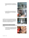
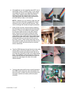
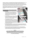
l. Fasten the Thermal Limit Switch to the flange on the
burner web using two self-drilling fasteners provided
in the Pitco Self Cleaning Burner System Kit.
Connect the leads of the SCBS Harness to the tabs
on the Thermal Limit Switch. Re-attach the drain
handle.
You have now successfully installed the Pitco Self-Cleaning Burner system. Apply the schematic label
provided with the kit over the one on the inside of the appliance door. Before proceeding it is highly
recommended that you now thoroughly check the appliance to insure that the procedure was
properly followed. Check that all gas joints are tight, all electrical connections are correct, and
that the appliance is completely and properly reassembled.