


PWM-T210
Installation Instructions Page 7
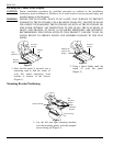
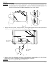
1. Align the center viewing port from the
carton template to the wall. Match the
center of viewing port to the center of
viewing height desired (Figure 7).
2. Mark a line on the bottom of the
carton template (Figure 8).
Marking the Wall
CENTER OF VIEWING HEIGHT DESIRED
CENTER OF
VIEWING LINE
VIEWING PORTS
MARKING THE
LINE
Figure 8
Figure 7
Wall Structure
Mark the Wall
Viewing Port
Center
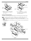
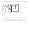
Marking the Bottom Mounting Points
CAUTION: The lag bolts must be secured to the center of a stud. Use a commercially available stud finder to locate the studs
nearest to your center viewing mark.
1. Place the upper portion of the bottom wall
plate to the reference line and mark the four
(4) lag bolt mounting points through the
wall plate slots on the wall (Figure 9).
2. Level the wall plate with the reference
arrow pointing up to the ceiling.
16"
Wall Plate
Mounting Slots
Wall Structure
Level
Figure 9
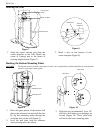
3. Pilot holes are recommended. Use a 1/4”
drill bit to drill where your markings are
located (Figure 10). These pilot holes
will be for the lower mounting plate.
Figure 10
Pilot Holes
Drill Gun