


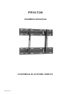
PWM-T210
Page 6 Installation Instructions
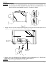
Figure 6
L
C
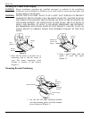
4. Match the center of viewing guide
with the center line you marked in
step 1 (Figure 4).
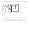
5. The mounting brackets are designed
with a center of viewing guide on the
side of them (Figure 5).
Figure 4
Figure 5
Display
Bottom
Align the
Mounting
Brackets
Center of
Display
Viewing
Guide
Center
Display
Bottom
Mounting Bracket
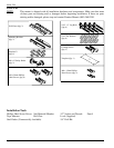
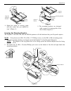
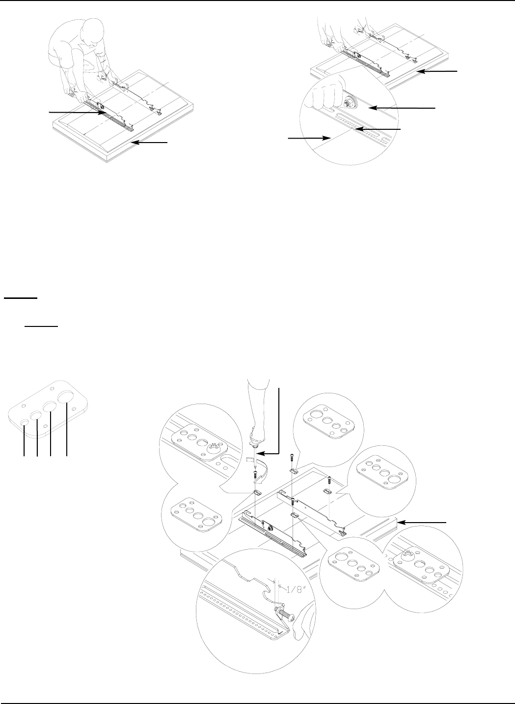
Securing the Mounting Brackets
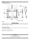
The Griplates™ have M4, M5, M6 and M8 hole patterns to fit the hardware that your flat panel requires.
NOTE
: Your plasma uses M8 x 20 or M6 x 12 Phillips screws, use the M8, or M6, mounting points.
1. Once the mounting brackets are aligned secure the Griplate™ to the flat panel (Figure 6).
NOTE
: The dimples of the top plates have to be facing up and the bottom dimples must be facing
down.
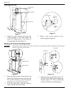
2. Pre-install two (2) M6 x 30 (mm) Phillips pan screws to the bottom of the left and right hand side
mounting brackets.
DIMPLES
FACING UP
DIMPLES
FACING DOWN
DIMPLES
FACING UP
DIMPLES
FACING DOWN
Screwdriver
Display Bottom
M4
M5
M6
M8