


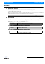

Connecting to the DMX512 Network 7
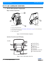
PLCYC LED Luminaires
Installation & User’s Manual
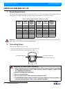
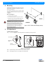
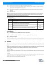
If the unit is supplied with an AC input cable but you did not order an AC input connector, Table 2 describes how to
connect power to your PLCYC LED Luminaire. Field wiring of the PLCYC LED Luminaire is straight forward. A
total of 3 wires/conductors need to be brought to the unit. The following wiring scheme is required:
Table 2: PLCYC LED Luminaire AC Input Connections
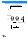
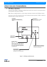
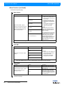
3. Connecting to the DMX512 Network
Basic DMX512 installation consists of connecting multiple PLCYC LED Luminaires together (up to 32 luminaires)
in "daisy-chain" fashion. A cable runs from the control console (or DMX512 control source) to the DMX connector
on the first PLCYC LED Luminaire. Another cable runs from the other DMX connector on the first unit to a DMX
connector on the next PLCYC LED Luminaire (or DMX512 device to be controlled).
Note: For more information on DMX512 networking and systems, refer to "Additional Resources for DMX512" on
page 1. For PLCYC LED Luminaire DMX Mapping, refer to "DMX CONTROL" on page 17.
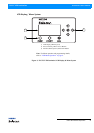
Figure 4: PLCYC LED Luminaires - DMX512 Connections
Wire Colour Purpose
Brown Main / Line (100 to 240VAC)
Blue Neutral
Green/Yellow Ground
DMX512
DMX512 (out from first
to second luminaire)
DMX512 (out to the next luminaire or DMX512
controlled device)
PLCYC LED Luminaires
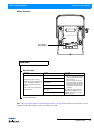
DMX512 Connections
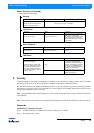
Note: Remaining pins on each connector are not used.
DMX512 Signal XLR Pin
Common (Drain) 1
DMX512 - 2
DMX512 + 3
(from console or
control device)