


Philips ProBridge 10 0150-0241B
4 Unit Settings
4.1 Configuring ProBridge Jumpers
The unit ships from the factory with the correct settings for most applications and
should not require the installer to open the unit and change the jumper settings.
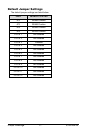
However, for trouble shooting purposes we have included the default jumper
settings.
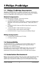
Opening The ProBridge
Place the ProBridge unit face down.
Using a small Phillips screwdriver,
carefully remove the screws located
near each corner of the unit. Once
the screws have been removed, lift
the cover to detach.
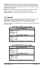
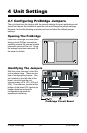
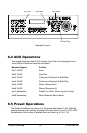
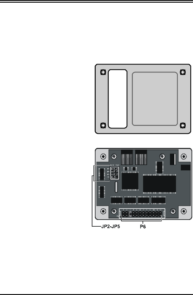
Identifying The Jumpers
With the cover removed, orient the
unit as shown here. There are two
sets of configurable jumpers. One
set, located on the left side of the
board, controls how the unit
communicates (JP2, JP3, JP4 and
JP5). The other set, located at the
bottom of the board (P6, twelve pin
header) determines specific
configuration elements for
equipment interfacing.
ProBridge Circuit Board