


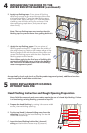
K. Double Doors Only:
Designer Series®: Place a dab of sealant into the center sill
VWULNHKROHDQGLQVWDOOWKH[ŶDWKHDGFRUURVLRQUHVLVWDQW
VFUHZVSURYLGHGRUDPDVRQU\VFUHZVLQWRWKHKROH
ProLine®: Remove the screw from the sill strike located on
the door sill, then place a dab of sealant into the sill strike
KROHDQGLQVWDOOWKH[ŶDWKHDGFRUURVLRQUHVLVWDQWVFUHZ
SURYLGHGRUDPDVRQU\VFUHZLQWRWKHKROH
Entry Doors: Remove the two screws from the sill strike
located on the door sill. Place a dab of sealant into the
FHQWHUVLOOVWULNHKROHDQGLQVWDOOWKH[ŶDWKHDG
FRUURVLRQUHVLVWDQWVFUHZVSURYLGHGRUDPDVRQU\
screws into the hole.
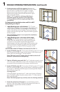
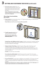
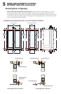
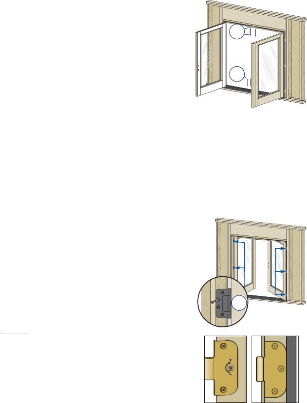
L. Double Doors Only: Shim between the frame and the rough opening at the head strike
ORFDWLRQDQGDWHYHU\IUDPHDQFKRUKROHORFDWLRQ.HHSVKLPVEDFNIURPLQWHULRUIDFHRI
the door frame.
Designer Series:,QVWDOOWKH[ŶDWKHDGFRUURVLRQUHVLVWDQWVFUHZVSURYLGHGLQWRWKH
hole.
ProLine:5HPRYHWKHVFUHZIURPWKHKHDGVWULNHORFDWHGRQWKHGRRUKHDGWKHQLQVWDOOWKH
[ŶDWKHDGFRUURVLRQUHVLVWDQWVFUHZVSURYLGHGLQWRWKHKROH
Entry Doors: Remove the two screws from the head strike located on the door head. Install
WKH[ŶDWKHDGFRUURVLRQUHVLVWDQWVFUHZVSURYLGHGLQWRWKHKROH
Note: For doors with pre-drilled installation holes in the head. If installation holes are
present, drill 1/8" diameter pilot hole into the rough opening and install a #8 x 3" corrosion
resistant screw (provided) in each hole.
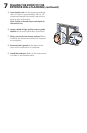
02QHDFKKLQJHVWDUWLQJDWWKHWRSLQVHUWDFRUURVLRQUHVLVWDQW
VFUHZ[SURYLGHGLQWRWKHRSHQVFUHZKROH0DNHVXUH
the screw passes through the shims and into the structural
framing.
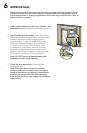
N. Check door operation. Open and close the door to check for
SURSHURSHUDWLRQ0DNHVXUHWKHGRRUZLOOODWFKFRUUHFWO\
Note: If there are any problems with the operation, check to
confirm the door frame is installed plumb, level and square.
If the reveal between the door panel(s) and frame is not
even, adjustments may be made:
Doors without adjustable hinges: Plastic shims located
behind the hinges may be removed to adjust the reveal
between the door panel and door frame. Additional hinge
shims may be added if required.
Note: Doors with adjustable hinges will have a (+)(-) on the
door panel hinge leaf to indicate possible adjustments and
doors without adjustable hinges do not have adjustment
indicators.
Adjustable hinges are not designed to make up for incorrect
installation of a door frame. Before adjusting hinges, confirm
the door is installed plumb, level and square.
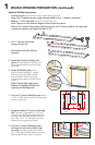
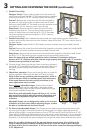
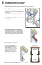
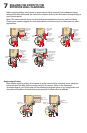
O. For Doors with adjustable hinges: The hinges can be used to move the panel side to side
by moving all hinges in the same direction or the hinges can slightly rotate the panel by
DGMXVWLQJWKHKLQJHVLQRSSRVLWHGLUHFWLRQV8VHD77RU[ZUHQFKIRU(QWU\'RRUVRUD
Allen wrench for Designer Series doors to turn the center screw clockwise (+) to increase the
space between the hinge side of the frame and door panel. Turn the center screws counter-
clockwise (-) to decrease the space between the hinge side of the frame and the door panel
.
Note: Do not adjust the hinge with the top and bottom screws loose; this could force the
hinge to adjust beyond its design capability which can cause the hinge to bind, damage
the hinge and/or pull out the screws. A 3/4 turn of the center screw provides approximately
5/32" adjustment.
Adjustable
Hinge
Non-Adjustable
Hinge
Interior
3K
3J
3L
3K
Interior
3L
3M
3
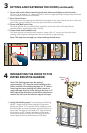
SETTING AND FASTENING THE DOOR (continued):